diy solar

diy solar

2 AWG 2 wires vs 4/0

AndyRonLI

Solar Enthusiast
Joined
Mar 13, 2021
Messages
189
Folks,
I have pretty cramped electric compartment in a fifth wheel.
I am using 4 200ah Amprer/Li-Time batteries in parallel.
I have am using the Victron Lynx Shunt and Distributor Sytstem.
I am running a 4/0 cable from Battery 3 neg to the neg of the Shunt
I planned on running 4/0 cable from Battery 2 positive to a battery isolation switch
And then another piece of 4/0 from the switch to the positive of the shunt.

That 4/0 is just brutal to bend. The isolation switch has two output terminals.
That got me thinking I might be better off running 2 AWG 2 lines from the switch to the shunt.
That makes the whole thing a lot easier to wire, but I end up with a system with wire rated for 200 A on a 400 A fuse.

Any thoughts? I have seen it done, I know its not ideal but how bad an idea is it?
Thanks
ANdy
 
You might look into welding cable for flexibility. As far as running two #2 in parallel, I wouldn't. I realize this is a mobile install, but the NEC prohibits parallel conductors when the overcurrent protection (400A) exceeds the ampacity of any paralleled conductor. The reason is one will invariably conduit more current than the other and if one is compromised the full 400A will be transferred to the remaining #2. If the fuse doesn't open, aka the fault is 400A, the insulation will likely catch fire.

Also, I'm not familiar with your shunt, but are you sure you wire both positive and negative to it? Shunts I use are wired in series with the battery, not across it.
 
Folks,
I have pretty cramped electric compartment in a fifth wheel.
I am using 4 200ah Amprer/Li-Time batteries in parallel.
I have am using the Victron Lynx Shunt and Distributor Sytstem.
I am running a 4/0 cable from Battery 3 neg to the neg of the Shunt
I planned on running 4/0 cable from Battery 2 positive to a battery isolation switch
And then another piece of 4/0 from the switch to the positive of the shunt.

That 4/0 is just brutal to bend. The isolation switch has two output terminals.
That got me thinking I might be better off running 2 AWG 2 lines from the switch to the shunt.
That makes the whole thing a lot easier to wire, but I end up with a system with wire rated for 200 A on a 400 A fuse.

Any thoughts? I have seen it done, I know its not ideal but how bad an idea is it?
Thanks
ANdy
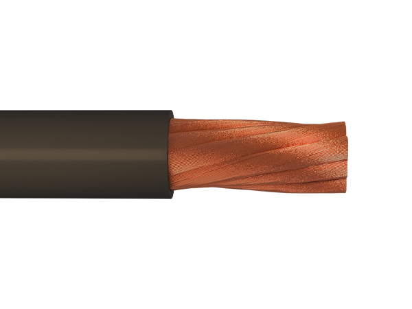
I use welding cables for all my DC wiring. They've high strand count and are very flexible. These also have generally have high ampacity for same gauge wire. If you buy them from welding stores (and not amazon etc), they come out a lot cheaper too.
 
I get my Class K welding cable in red, black, and green from these guys.
Price was reasonable at the time, can‘t say if it still is.
 
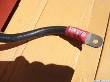
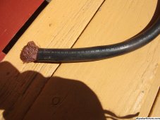
So I had the cables made by Current Connected. There wire is something called Power-Flex.
Would welding cable be more flexible?
Andy
 
Correct on the UL stuff, unless you can find it listed as a recognized wire type, like RHW, etc. A close cousin is DLO cable, which is RHH/RHW but it is more expensive. here's a linkhttps://1xtechnologies.com/dlo-cable/
 
That 4/0 is just brutal to bend
Another idea:

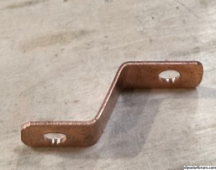
This is what I did in an RV because things were so tight, I was able to offset and rotate to get things where I needed them.

This is copper bar stock from McMaster Carr. I put it in a bench vise and got creative. I was only the 200 amp range though.

1695944061740.png
 
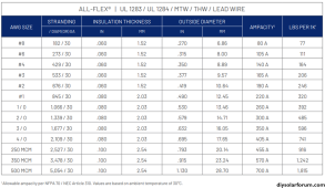
NEC Table 310.17 shows 405A for 90C 4/0 Cu in free air
FYI the NEC defines free air as:

Free Air (as applied to conductors). Open or ventilated environment that allows for heat dissipation and air flow around an installed conductor.

In this case I'm not sure wires in a cramped battery compartment meet that definition. Also in most cases the NEC only allows use of 60 and 75c temperature ratings for ampacity(110.14_(C))
 
...the NEC prohibits parallel conductors when the overcurrent protection (400A) exceeds the ampacity of any paralleled conductor.
FWIW, paralleling larger conductors without fusing is fine by the NEC, but the lower limit is #1AWG. You do have to be careful of how the cables are run.
 
FWIW, paralleling larger conductors without fusing is fine by the NEC, but the lower limit is #1AWG. You do have to be careful of how the cables are run.
1/0?

Combined OCPD is allowed to be the paralleled ampacity, with some conditions of use (?) saying you need to wire it up correctly to even out the current, like similar length and interleaving the conductors at all splice points.

Also as you parallel you hit the current carrying conductor derate.

Not that most battery wiring efforts on the forum and YouTube follow NEC.
 
Back
Top