diy solar

diy solar

DIY busbars... 4/0 awg

ericfx1984

Solar Enthusiast
Joined
Oct 10, 2021
Messages
741
I'm planning to build some bus bars... I will be feeding two, 1/0 gauge cables from a pair of batteries on one end into a 4/0 gauge cable to an inverter on the other end

Of course there will be various other connections made on these busbars as well...

I'm wondering if a 2-in wide x 1/8" flat copper bar would be appropriate for this? I may need to bring it up to 1/4" But that's not the part I'm particularly worried about... I'm wondering if 2-in wide would be wide enough to successfully interface with a 4/0 cable?
 
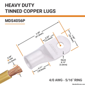
To decide on the width necessary you should first decide on the lugs, that will define their contact area and bolt size.

To decide on the thickness of the bar you should compare the cross sectional area of the copper bar to a 4/0 cable.

1699376841183.png

I'm not recommending these lugs just showing what information you would gather from a lug selection.

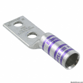
If I was going to the effort of DIY'ing this I might look at double bolt lugs for 4/0.
 
Mechanically, 2" is plenty to attach a 4/0 lug to. Electrically what's important is the cross-sectional area of the bar. 2" x 1/8" = 0.25 in² = 318,309.89 circular mils. A 4/0 cable is 211,592 circular mils, so your busbar has a cross-sectional area of about 1.5 times your cable.
 
This is what I used to use. Got from Amazon. Says unavailable now, but must be available somewhere. Its all you will ever need.


SCGB-1KT - .25" x 2" x 10" Copper Ground Bus Bar Kit - UL Listed - Wall/Surface Mount - Kit Includes Mounting Brackets, 2.5kV Insulators, Hardware
 
This is what I used to use. Got from Amazon. Says unavailable now, but must be available somewhere. Its all you will ever need.


SCGB-1KT - .25" x 2" x 10" Copper Ground Bus Bar Kit - UL Listed - Wall/Surface Mount - Kit Includes Mounting Brackets, 2.5kV Insulators, Hardware
Too many holes taking away from the contact patch
 
I wouldn't worry about size of contact patch, or a brief neck down.
In fact, actual contact is a tiny fraction of the area you see, and depends on force.
I worry more about sufficient clamping force.

Copper can handle the current. Heat buildup would be the concern for something small, but unlike a continuous piece of small cross section, heat gets to spread out in copper, not just flow in one direction. So contact patch or neck doesn't require area nearly as large as cross-section of wire with sufficient ampacity.

Think of how small the contact patch is for a relay, especially with curved contacts.
Look at how small the braid wires are in the relay.

Cross section and ampacity refers to a long run. Per NEC, conduit fill derating doesn't apply under 2' length.
 
Too much missing surface area on the contact patch and to small of bolt holes for 4/0
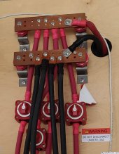
You're a funny guy. I ran a 44,000 watt FLA battery bank through these buss bars. All connected with 4/0 wire and copper lugs. 4 strings at 48 volts nominal and 1 connection to the inverter. Total amperage was 900 amps. These buss bars never even got above room temperature. You must not understand these are 1/8th thick solid copper. And they are pre drilled to allow connection to several strings.
In the photo, they are connected with Blue Sea systems DC ON/OFF switches allowing each string to be turned off individually. And each string was protected with a 150 amp DC terminal fuse. Never an issue.
 

Attachments

  • buss bars.jpg
    buss bars.jpg
    688.7 KB · Views: 90
You must not understand these are 1/8th thick solid copper. And they are pre drilled to allow connection to several strings.
In the photo, they are connected with Blue Sea systems DC ON/OFF switches allowing each string to be turned off individually. And each string was protected with a 150 amp DC terminal fuse. Never an issue.
Actually most of the product stock photos do not show them with connections already made... This causes me to think that they are smaller... Your picture on the other hand really helps me to better understand the physical size of the busbar and the hole spacing

Based on your pictures I think they would work quite well and honestly are about the same price as making them myself

Thank you
 
I was going to make my own as well but off the shelf was way to easy...
GOUNENGNAIL- 10" Copper Ground Bar Kit,900A Grounding Busbar Bar with UL Recognized SM40 Insulators Rated Uimp up to 7.2KV https://a.co/d/gKEZdgM

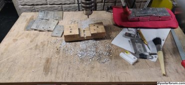
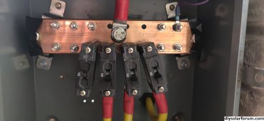
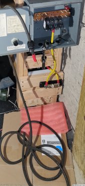
Edited to remove photo containing my address.
 

Attachments

  • IMG_20231101_184433.jpg
    IMG_20231101_184433.jpg
    1.1 MB · Views: 68
  • Screenshot_20231112-174312.jpg
    Screenshot_20231112-174312.jpg
    544.3 KB · Views: 40
Last edited:
I was going to make my own as well but off the shelf was way to easy...
GOUNENGNAIL- 10" Copper Ground Bar Kit,900A Grounding Busbar Bar with UL Recognized SM40 Insulators Rated Uimp up to 7.2KV https://a.co/d/gKEZdgM
Has anyone actually load tested these? Am I crazy or does it seem like a lot less copper mass than something like the Blue Sea Systems 500A busbar?
 
(info discovered,,,,comment deleted)….
 
Last edited:
You're a funny guy. I ran a 44,000 watt FLA battery bank through these buss bars. All connected with 4/0 wire and copper lugs. 4 strings at 48 volts nominal and 1 connection to the inverter. Total amperage was 900 amps. These buss bars never even got above room temperature. You must not understand these are 1/8th thick solid copper. And they are pre drilled to allow connection to several strings.
In the photo, they are connected with Blue Sea systems DC ON/OFF switches allowing each string to be turned off individually. And each string was protected with a 150 amp DC terminal fuse. Never an issue.
Umm, it's the amount that passes thru that matters not the amount the batteries could produce if you shorted them or something. You might have 1000 amps of available battery but unless your single inverter was pulling 48000 watts you never got anywhere close to that. With two 50a/240v inverters I need a bus capable of handling 24000 watts. That's 48v at 500A, generally closer to 50v and maybe 550 with production loss assuming you were wide open pulling 240/100a for any length of time. I have an 800A bus bar. I can hook 500 100A batteries to it, as long as my charge rate or draw rate is fused/breaker'ed to limit the draw across the bus to 800A. Whatever you use for batteries needs to be able to handle the greater of the draw / charge rate between the bus and the batteries. After that you are just getting a bigger tank, you don't need a bigger hose. If you were pulling 900A anywhere your big bus bars would not be room temperature, but they would likely only be warm around the cable ends that were handling the load.

I'd like to hear what one might be doing that pushes 900A in either direction. The highest charge rates I've seen from my setup is around 12KW from a little under 18KW of panels. That's roughly 250A. I have hit 17 or 18KW out powering loads from the batteries, though not for long. That would be about 325A or so. Make sure you have breakers/fuses that match each feed wire. Now if you throw up 50KW of panels, and you have the mppt to process it, you might get up to 1000A, but I've not seen anyone bragging on that much solar output. Just grab a 600A or 1000A bus bar unless you have over 100A or 150A of load.

Your going to have to parallel 4 240v 50A inverters to need a 1000A bus.
 
If you connect in the order Battery Battery Inverter Inverter, all current goes through busbar cross section.
Connected Battery Inverter Inverter Battery, no part of the busbar carries more than half the current.

I was able to put lugs on top and bottom of busbar.
My setup is [Inverter/Inverter] Battery [Inverter/Inverter] for negative.

Inverter/Inverter Fuse Battery Fuse Inverter/Inverter for positive
(Two short cables spread out from battery to two fuses, and two inverters connect to each fuse.)
 
Cross section and ampacity refers to a long run. Per NEC, conduit fill derating doesn't apply under 2' length.
I’m not home with my book (and being lazy). Can you post that section? Thanks.

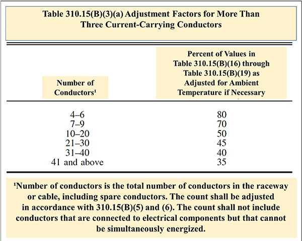
310.15(B)(3)(a) Adjustment Factors for More Than Three Current-Carrying Conductors.​

Use the image to help answer the question.


Click to Enlarge
Use the image to help answer the question.

Table 310.15(B)(3)(a) provides adjustment factors when installing more than three current-carrying conductors (CCC). Years ago, the table only applied when there were more than three CCC “in a raceway or cable”. The adjustment factors in the table are required for more than just raceway or cable installations containing more than three CCC.
A good example of this is when separate cables are installed without maintaining spacing. For these installations, if cables are bundled for a continuous length longer than 24 in., the allowable ampacity of each conductor must be reduced as shown in Table 310.15(B)(3)(a).
The table also applies to spare conductors. Often, spare conductors that have been installed for future use will eventually become current carrying conductors.
The table does not apply when conductors cannot be energized simultaneously. For example; There is no need to consider two travelers to a 3-way switch as two current carrying conductors since only one of the two can be energized at any given time.
It is important to remember that temperature correction and adjustment factors are permitted to be applied to the ampacity column in Table 310.15(B)(16) for the specific temperature rating of the conductor, as long as the corrected and adjusted ampacity does not exceed the ampacity for the temperature rating of the conductor terminal in accordance with 110.14(C).
For example, an 8 AWG, THHN copper conductor has an ampacity of 55 amps in the 90°C column of Table 310.15(B)(16) and 50 amps in the 75°C column.
If the 90°C wire is connected to a circuit breaker marked with 75°C terminals, and installed in a raceway with a total of 4 CCC (which requires an 80% adjustment factor), then the math can begin at the maximum rating of the wire which is 55 amps as long as the final adjusted value does not exceed 50 amps in the 75°C column since the lower temperature rated terminals are the weakest link in the circuit:
55 X 80% = 44 amps.
 
Back
Top