That is not a MPPT controller. It is a known fake. It is a PWM controller. You never see USB plugs for charging on a MPPT.
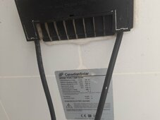
With that controller, you MUST use 24V panels that typically have 72 cells with a Vmp around 36V. Your panel is a 60 cell panel. In moderate to warm conditions, that panel won't be able to reliably charge your battery. As heat increases, Vmp decreases. Vmp must be at least a little above voltage.
Will has several diagrams on his site
'known fake', yes I saw a mention of that and conceded, I probably got what I paid for.
It worked when charging one 12v battery, but yes might struggle with two, even in our Spanish sun.
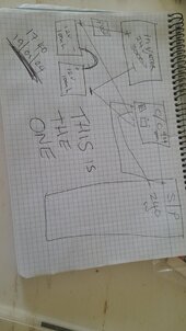
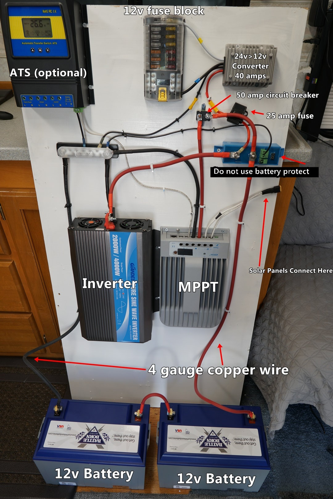
I will largely stick with my partners wiring for one 12v battery, done before setting off to work away
(will review diagrams on the site, thank you for those given, seen some that contradict each other, with Inverter coming from the controller).
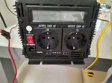
It's just a temporary home, so been to charge phones etc... but it would be nice to run a fridge or if lucky, a freezer.
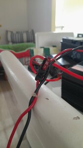
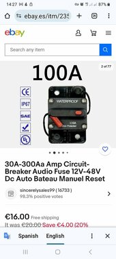
Will note to hook up the battery to it first/to detect battery voltage, once I add the second 12v battery in series with Terminal Connectors I got and a 150amp fuse, thank you.
Will consider adding a second panel in series and changing to a MPTT, Victron 100/20
Victron 100/20
Our biggest disappointment is the friend helping with supplying our little house, has twelve used Solar Batteries going wanting.
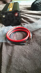
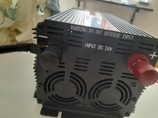
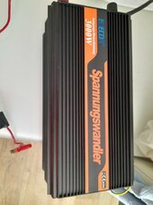
We imagined discarding our 100ah 12v for one of her lovely 1220ah ones with our current single 240w Panel. Even updating our 12v Inverter to a 24v one, on a kind neighbours advice.
Now we realise that we would need to move and use ALL twelve of the monster 2v Solar Batteries to reach 24v and cover the house with enough panels to hide it from even the Space Station.
Like Penicillin... we have given up understanding why we cannot use any of hers and just reluctantly bought a second 12v battery.
We might go 'Full Monty' if we are here longer, but right now, if feels like an enterprise that would give an 'Aspirin a Headache' Lol


 not quite that much. You can probably get away with as little as 1500W.