Yurtdweller
Solar Enthusiast
I'm reconfiguring my system.
It needs to be portable.
I've built a 1180ah 12v battery in a road case.
I'm building a cabinet for the inverter (straight 2kw inverter, psw) and the charge controller.
It will be connected to the battery by cable umbilical.
Question is this:
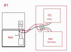
option #1-for most convenience, I could connect the charge controller (100amps max) directly to the back of the inverter (cabled for 166 amps, min)
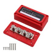
and connect the inverter's leads to the battery by terminal blocks or by anderson connector.
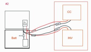
Option two: seperately connect both inverter and cc to battery terminals by terminal blocks or anderson connector.
I understand that option two is technically slightly better, but only by about a foot of cable run, at the expense of having a slightly less streamlined assembly.
I suppose wiring them separately would allow each device to have it's own fuse. ?
Are there any other potential electrical reasons not to connect things like in option #1?
Second question:
The system moves about 5 times a year. Quick connection is not strictly necessary. Merely for convenience. I've never used Anderson connectors. Is it worth the extra expense?
Am I overlooking anything in terms of connecting these components to the battery?
Thanks group


