diy solar

diy solar

Connecting Neutral/Ground terminals to DC input negative terminal on Growatt SPF 3000TL LVM-48P?

Jbofill

New Member
Joined
Aug 2, 2023
Messages
7
Location
Colorado
Hello all I'm new here and have a question regarding wiring my Growatt SPF 3000TL LVM-48P.

I came across this thread https://diysolarforum.com/threads/growatt-3000-spf-floating-neutral-solved-for-now.31692/ and have determined that my unit does not internally bond neutral and ground and plan to go ahead bond those myself as recommended by the diagrams in that thread.

Now I am wiring this unit up in an RV. In my setup I plan to wire the AC out to the RV's AC breaker panel where the ground bus is connected to the RV chassis. I also want to power the RV's DC circuit's off of the same battery that will power the inverter (through step down to 12v converter). Now as it is the DC circuits also run through the RV's chassis (on the negative side).

I already posted in the original thread here https://diysolarforum.com/threads/growatt-3000-spf-floating-neutral-solved-for-now.31692/post-844617 but this diagram sums up how it would be wired and clarifies my concern.
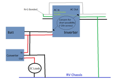
2fuu941k.png

Does anyone know if this configuration is safe for the unit to connect both the AC ground and in turn neutral (because neutral and ground will be bonded) to RV chassis and DC side battery negative to RV chassis at the same time? In essence, a connection will be created between the inverter's AC neutral out and it's negative DC input terminal through the RV chassis. When testing voltage between these two point I do see about 20v across them, so I am concerned that this configuration will cause short circuit and damage to the unit.

Thanks for any help.
 
First start off, I'm not American.
The whole concept of split phase and bonding neutral with a ground is blasphemy to me :)

There are 3 wires L (life) N (neutral) and G (Ground) and they should stay separated, always.

The L and N provide your alternating current.
The G is for you protection, besides that the inverter might get charged by "phantom energy" (and give a nasty bite), if there is a problem this ground should safe your ass from being electrocuted.

Now I know in the states people like 110 and 240v, combine and split where they feel like it and love it.

If your inverter doesn't provide 110v, it's not a split phase, and should be treated as regular, normal AC inverter.
220-240v, 50-60 hz output.

That means no combining the ground and neutral!!!!

The 2 wires L ,N and G go to your electrical appliances. 3 wire cable.

The grounding / "earth" is usually a meter long copper stick in the ground
(Henceforth the word.. grounding)

Your RV is on rubber, and sticking a rod in the soil is limiting your movements:)

There are those rubber with iron/brass "anti static strips" that you can connect to your car to have it contact with the earth (ground)

It won't be as good as a copper rod, but some is better then nothing.

You probably already have one for the chassis of the RV to release its "phantom charge".

You can attach a second one, obviously not combined with the neutral.

Neither the neutral of the car, or the neutral or the neutral of the inverter!!

 
First start off, I'm not American.
The whole concept of split phase and bonding neutral with a ground is blasphemy to me :)
If your grid provides you with a line, neutral, and ground. Your neutral and ground are bonded. The grid does it for you.
In North America, we do it at the service panel. Because the grid suppliers figured out how much money they could save on one less wire to each service.
 
First start off, I'm not American.
The whole concept of split phase and bonding neutral with a ground is blasphemy to me :)

There are 3 wires L (life) N (neutral) and G (Ground) and they should stay separated, always.

The L and N provide your alternating current.
The G is for you protection, besides that the inverter might get charged by "phantom energy" (and give a nasty bite), if there is a problem this ground should safe your ass from being electrocuted.

Now I know in the states people like 110 and 240v, combine and split where they feel like it and love it.

If your inverter doesn't provide 110v, it's not a split phase, and should be treated as regular, normal AC inverter.
220-240v, 50-60 hz output.

That means no combining the ground and neutral!!!!

The 2 wires L ,N and G go to your electrical appliances. 3 wire cable.

The grounding / "earth" is usually a meter long copper stick in the ground
(Henceforth the word.. grounding)

Your RV is on rubber, and sticking a rod in the soil is limiting your movements:)

There are those rubber with iron/brass "anti static strips" that you can connect to your car to have it contact with the earth (ground)

It won't be as good as a copper rod, but some is better then nothing.

You probably already have one for the chassis of the RV to release its "phantom charge".

You can attach a second one, obviously not combined with the neutral.

Neither the neutral of the car, or the neutral or the neutral of the inverter!!

Thanks for your response, however I think there are some misconceptions here. From my understanding in an AC system the ground wire exists to protect in cases of ground faults, which essentially provides a low resistance path back to the source if the “line” somehow comes into contact with the case of an appliance and energizes it, and it needs to be connected to neutral to complete this circuit, otherwise the ground wire is useless. That is the whole reason for ground-neutral bonding and why the “ground” wire even exists.

With this specific unit it does not do that on its own and the original thread that I linked details this and recommends the wiring I show (specifically jumping the neutral in- neutral out and bonding ground-neutral). For clarity I am not talking about “earth grounding” I am talking about the ground conductor in the system which in this case is coming from the ground terminals on the inverter itself.

Also this unit is not split phase nor a 240v inverter. It is 110-120v single phase.
 
Hello all I'm new here and have a question regarding wiring my Growatt SPF 3000TL LVM-48P.

I came across this thread https://diysolarforum.com/threads/growatt-3000-spf-floating-neutral-solved-for-now.31692/ and have determined that my unit does not internally bond neutral and ground and plan to go ahead bond those myself as recommended by the diagrams in that thread.

Now I am wiring this unit up in an RV. In my setup I plan to wire the AC out to the RV's AC breaker panel where the ground bus is connected to the RV chassis. I also want to power the RV's DC circuit's off of the same battery that will power the inverter (through step down to 12v converter). Now as it is the DC circuits also run through the RV's chassis (on the negative side).

I already posted in the original thread here https://diysolarforum.com/threads/growatt-3000-spf-floating-neutral-solved-for-now.31692/post-844617 but this diagram sums up how it would be wired and clarifies my concern.
View attachment 163095

Does anyone know if this configuration is safe for the unit to connect both the AC ground and in turn neutral (because neutral and ground will be bonded) to RV chassis and DC side battery negative to RV chassis at the same time? In essence, a connection will be created between the inverter's AC neutral out and it's negative DC input terminal through the RV chassis. When testing voltage between these two point I do see about 20v across them, so I am concerned that this configuration will cause short circuit and damage to the unit.

Thanks for any help.
I think that you are going to have to contact Growatt on this. I'm not sure if it will be okay with the battery negative being grounded.
Victron is designed for the mobile setup. I'm not sure if Growatt is.
 
I think that you are going to have to contact Growatt on this. I'm not sure if it will be okay with the battery negative being grounded.
Victron is designed for the mobile setup. I'm not sure if Growatt is.
Yeah I have also messaged Growatt and am waiting to hear back from them. Hopefully they respond. Just wanted to see if anyone here has any insight. Thanks.
 
Thanks for your response, however I think there are some misconceptions here. From my understanding in an AC system the ground wire exists to protect in cases of ground faults, which essentially provides a low resistance path back to the source if the “line” somehow comes into contact with the case of an appliance and energizes it, and it needs to be connected to neutral to complete this circuit, otherwise the ground wire is useless. That is the whole reason for ground-neutral bonding and why the “ground” wire even exists.

With this specific unit it does not do that on its own and the original thread that I linked details this and recommends the wiring I show (specifically jumping the neutral in- neutral out and bonding ground-neutral). For clarity I am not talking about “earth grounding” I am talking about the ground conductor in the system which in this case is coming from the ground terminals on the inverter itself.

Also this unit is not split phase nor a 240v inverter. It is 110-120v single phase.

In the states, sure probably they connect the neutral and ground for you.

In the rest of the world (220v) it's not. (!!!)

As soon as there is any bridging between the neutral & life and ground, the safety will engage.

If they where combined, then you have actually 2 neutral/ground wires and one life.

Combining would render one useless.
You would just be waisting copper.

In the states, do you use 2 or 3 wires at a grounded power socket?

The Americas and the rest of the globe have totally different ideas on how things should be wired, especially when it comes to Safety.

This is how things are wired outside the Americas.
3 different wires, each with their own separate function.

And yes, many low power consumption appliances use just 2, L&N.

More risk places like kitchen and bathroom, workplace, they all have that third wire, ground.
What has its own function connected to the residual-current device, what will save your ass if you try to electrocute yourself. (By accident off course)

In the rest of the world, sure after a nasty burn the normal L&N breaker will "eventually" stop the power, as you make a short.
With residual-current device and that special ground wire (usually green/yellow) you just feel a pinch.

The main real life difference between 2 wire power sockets and grounded power sockets, tested by yours truly :)

Like I said... I'm not from the Americas, and there is a lot of discussion possible about who is wright or wrong.

They are both wright and wrong, depending on your point of view.

I'm not debating on how it should work, just writing how it does work in the rest of the world and the main idea behind it.

Mixing DC and AC neutral, that doesn't seem like a good idea.
Especially that if you measure, there is a voltage difference.

If the growatt didn't combine the ground and neutral, I guess they have a good reason to NOT do this.
Unless you are sure you have better qualifications then the Growatt engineers ad they build and sold thousands of unite wrong.

The inverter will charge the casing.
Electromagnetic field and such.

One of the reasons an inverter should be grounded.
It should be able to release this build up charge.

Some inverters "leak" more then others.

Also not a discussion, but stating a fact that metallic casing of electronics can and will hold a charge.
In some situations this can be a significant charge.

It does not matter what brand, this is just a fact in life.
That is why the unit needs a ground.

For your own safety..
residual-current device breakers..
They have, in the rest of the world, a ground wire.

How you want to combine it in the Americas... your party ? :)

I hope I never need to do any electronic wirering there hahaha..
I probably black out a whole block.

But this is how the wiring works outside America.
L and N provide the power.
G the safety ( if it's connected /combined / setup with a residual-current device and obviously breaker.)
 
In a RV the vehicle metal, body, frame is your 'ground' not the dirt outside.
There is no problem having the AC protective earth cable and the house and vehicle connected to the RV 'ground'.

Neutral bonding is a seperate issue. In the diagram there is a serious error , remove the link in the neutral wire that connects inverter input to output.

Unless the Growatt has automatic neutral to earth bond internal relay that performs the bond only when in stand alone mode, you cannot have a bonded system in your RV.
 
Can you explain specifically why you want neutral and ground bonded in the RV?

When you are plugged into the utility, the neutral and ground are going to be bonded at their main service entrance panel.
You should (almost) never connect neutral and ground further downstream of that.

The key word here, is "almost". There are very specific times you may want to, but a lot of people think they need to be bonded "just because", which isn't accurate.

Anyway, can you expand on why you'd like to tie them in together/bond them?
 
In a RV the vehicle metal, body, frame is your 'ground' not the dirt outside.
There is no problem having the AC protective earth cable and the house and vehicle connected to the RV 'ground'.

Neutral bonding is a seperate issue. In the diagram there is a serious error , remove the link in the neutral wire that connects inverter input to output.

Unless the Growatt has automatic neutral to earth bond internal relay that performs the bond only when in stand alone mode, you cannot have a bonded system in your RV.
Yes I understand that the RV chassis serves as “ground” in this case and not the dirt. But as stated in my earlier reply I am not talking about “earth ground” (or it’s equivalent). Anywhere I say “ground” I am talking about the ground conductor/ the ground terminals on the inverter.

Jumping the neutral terminals is not an error, it is intentional. This is the topic and findings of the original thread I linked. (See the first post)

This specific unit does not dynamically create or have any ground/neutral bond as also discussed in detail in the original thread. (TLDR: older versions of this model don’t do it, later hardware revisions do do this automatically. Mine is an old unit)

Can you explain specifically why you want neutral and ground bonded in the RV?

When you are plugged into the utility, the neutral and ground are going to be bonded at their main service entrance panel.
You should (almost) never connect neutral and ground further downstream of that.

The key word here, is "almost". There are very specific times you may want to, but a lot of people think they need to be bonded "just because", which isn't accurate.

Anyway, can you expand on why you'd like to tie them in together/bond them?
When not bonded the neutral is left floating relative to ground. There’s ~50v across them. That is the reason for bonding. Again this is in the original thread in the first post about the behavior of this specific inverter. It’s the main topic.

I understand that ground and neutral should be bonded at one and only one point in the system and that grid/utility/shore provides that bond.

To clarify, in my setup I do plan to create the bond dynamically using a relay (depending whether or not connected to grid) The specific wiring can be seen here
https://diysolarforum.com/threads/growatt-3000-spf-floating-neutral-solved-for-now.31692/post-385050
In my diagram didn’t include the relay and instead just show hardwired bond for simplicity’s sake in demonstrating my concern.

To sum up, the essence of the circuit (excluding the dc circuit) I showed comes from a previously discussed topic and testing done by other user on this specific inverter. From the findings it seemed like this was the best and recommended solution. My question was with the concern I had in my specific case (including dc circuits) when wiring according to this method (the ac side).

However, I may reconsider this approach. Maybe I should just not worry about the N-G bond or the bond between N-in and N-out and just let it float? The other possibility is just isolate the dc side by not going through the chassis at all.
 
Yes I understand that the RV chassis serves as “ground” in this case and not the dirt. But as stated in my earlier reply I am not talking about “earth ground” (or it’s equivalent). Anywhere I say “ground” I am talking about the ground conductor/ the ground terminals on the inverter.

Jumping the neutral terminals is not an error, it is intentional. This is the topic and findings of the original thread I linked. (See the first post)

This specific unit does not dynamically create or have any ground/neutral bond as also discussed in detail in the original thread. (TLDR: older versions of this model don’t do it, later hardware revisions do do this automatically. Mine is an old unit)


When not bonded the neutral is left floating relative to ground. There’s ~50v across them. That is the reason for bonding. Again this is in the original thread in the first post about the behavior of this specific inverter. It’s the main topic.

I understand that ground and neutral should be bonded at one and only one point in the system and that grid/utility/shore provides that bond.

To clarify, in my setup I do plan to create the bond dynamically using a relay (depending whether or not connected to grid) The specific wiring can be seen here
https://diysolarforum.com/threads/growatt-3000-spf-floating-neutral-solved-for-now.31692/post-385050
In my diagram didn’t include the relay and instead just show hardwired bond for simplicity’s sake in demonstrating my concern.

To sum up, the essence of the circuit (excluding the dc circuit) I showed comes from a previously discussed topic and testing done by other user on this specific inverter. From the findings it seemed like this was the best and recommended solution. My question was with the concern I had in my specific case (including dc circuits) when wiring according to this method (the ac side).

However, I may reconsider this approach. Maybe I should just not worry about the N-G bond or the bond between N-in and N-out and just let it float? The other possibility is just isolate the dc side by not going through the chassis at all.
I think that isolating the DC side is the best option.
As long as you don't need to use the DC directly for loads.
Instead of a DC-DC converter. Maybe use an AC-DC converter. It is slightly less efficient. But not by a lot.
 
@timselectric do you think that wiring up the AC as I’ve demonstrated is necessary (creating N-G bond with relay and bonding neutrals) or is it even a big deal if I just leave the neutral floating? I’m not sure if this essentially renders the ground conductor useless (specifically when not connected to grid)
 
Yes, I would do as you have described.
Grounding is for personal safety.
If your system is left floating. There is no ground. And yes, the ground conductor would serve no purpose.
 
Back
Top