diy solar

diy solar

Contactor relay - choice between charge and discharge protection

offgrider

New Member
Joined
Jul 20, 2020
Messages
65
I have an operational grid-tied solark12k maxed out on panels with 32 of the 280ah lifepos from lightning-power nearly ready to be connected. Planning on a 16s2p setup to export as little power as possible.

The Orion BMS people are working with me to get this Jr2 unit working with my Solark12k (Victron CAN protocol) and they are being very helpful with all my questions. But I have 1 final concern that I'd like to run through the group here - Now, normally the CAN bus will drive all battery operations, and we know the contactor is the last resort protection here; this particular BMS has 2 separate output signals for last resort protection: "charge enable" & "discharge enable" where I guess I have to pick 1 to use.

  1. Where if I pick the "charge enable" signal to drive my contactor, then whenever the BMS thinks the battery may be too full it will disengage that contactor, disconnecting my battery's terminal from the Solark. This can prevent my house from burning down by overcharging the batteries.
  2. And where if I pick the "discharge enable" signal to drive my contactor, then whenever the BMS thinks the battery may be too low it will disengage that contactor, disconnecting my battery's terminal from the Solark. This can prevent my batteries from ruining themselves by going too far below 2.5v.

But it seems I cannot have both types of protection? Is this normal for all other BMSs?

And lets say I pick #1 there since I hold my entire house as much more valuable than a forever useless battery bank.. Under regular operations would I ever be in a position where the sun is shining strong, the panels are providing all the power the house needs and have also just topped off the batteries and the BMS thinks to itself: "hey you know what, these batteries are full, I need to remove the signal from the charge enable pin" and if it does that, then my contactor de-energizes and the batteries are disconnected from the solark and I cannot even draw power from the batteris even though they are currently full? Or does it not work that way and the BMS only de-energizes the "charge enable" if it believe the solark has ignored CAN commands to stop sending current to the battery?
 
I'm using a ZEVA BMS that has the same arrangement with 2 contactor outputs. Since I'm only using a single contactor the power wiring for the contactor coil is looped through both photorelays on the BMS. So if either BMS relay opens then the contactor opens and the battery is disconnected from the inverter. If this happens it does require manual intervention to either charge or discharge the battery until its in range again and the BMS recloses the contactor. That is the downside of using only one contactor.
However, using 2 contactors then doubles your parasitic current draw since now 2 coils are energized all the time.
I solved the later issue by converting to a magnetic latching contactor with 0 stand by draw. It did require a separate PCB controller to provide the necessary bi-directional DC pulse to open and close.
 
I also use a ZEVA BMS, depending on your charge current you may be able to use a smaller contactor. I use gigavac minitactor on my charge side which has a lower coil draw than the discharge side higher current contactor.

I wouldn’t leave the battery unprotected from either scenario, either set it up as Bentley has described, or use 2 disconnects.
 
Can they combine them into a “BatteryOk”? That way if either side trips it cuts the battery.

Or do both (charger & loads) have a relay? So you can set either to kill the battery. This makes much more sense if you have a regular charger (SCC) and inverter.

This level of protection will likely never be used… unless something dies in your system. Then you really NEED it!

If the Can bus fails, does everything keep running?
That is the current question I have into them already since the BMS-Jr-2 has a few multipurpose outputs that can have some level of programming put on them. How intelligent that programming is would be the question, but that would be the elegant solution for sure. Ill repost back when I find out what can be done with those multipurpose outputs.

Ill have to ask Solark about CAN failures.
 
Ill have to ask Solark about CAN failures.

A BMS should be a stand-alone device that is taking its own measurements, has an onboard user menu, with memory, to set and hold warning and trip values and most importantly acts independently to disconnect the battery when any of the safety limits are reached. This relatively recent trend of having cross communication via RS485 or CAN between the Battery and Inverter is primarily an issue of convenience so the information and device menus can be viewed and changed without having separate apps. While its nice to have the SoC values from the BMS imported into the inverter so they can be viewed and/or used to trigger a recharge cycle an active communication link should never be a requirement for either the Inverter or BMS to do its job using its own settings.

With fully proprietary hardware where ALL the components are from a single company such as Enphase or Generac Etc, the foregoing may not be true which would in fact introduce another failure mechanism into the system. That being simply that a communication error prevented critical data from being transferred to another module that was no longer collecting this critical data itself.
 
On the Victron, with the CAN BUS from the bms. If the can-bus fails, the inverters and SCC’s go to their programmed values. So you want to program them exactly how you want them before working on the Can-bus. That way the can-bus fail mode is still really good for the batteries.

I installed a Batrium bms along with lots of Victron. When I was planning the system, I “knew” I wanted the can-bus running. I thought that was exactly what is needed. However, in the setup of the system, after I got everything running, I was not motivated to get the can-bus going. (Still not…)

Good luck with your project!
 
But it seems I cannot have both types of protection? Is this normal for all other BMSs?
I have a Chargery BMS with separate charge and discharge ports. One drives a discharge relay and the other a charge relay. Note I am using a all in one inverter which has one set of cables going to the battery so if the discharge relay opens it also interrupts charging. Not sure if that is the case with the solarark.
 
my solark also has only 1 set of cables for the battery so am in the same boat.
also my Jr2 bms's signal output for the gigavac contactor can only support 175ma which is well under what the gigavac that was provided in my kit requires, so im going to have to source another relay to stick in between the bms and the gigavac.
 
Last edited:
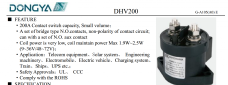
I used Dongya contactors; very low coil power. They have worked perfectly. I have one on the solar input to the inverter (overcharge); one on the battery input to the inverter (discharge)

1665152787045.png
 
I used Dongya contactors; very low coil power. They have worked perfectly. I have one on the solar input to the inverter (overcharge); one on the battery input to the inverter (discharge)

View attachment 115393
that one wouldnt work for me, its operating coil power is 200mw which means its pickup current is likely even higher. the orion requires pickup current to be < 175ma. im thinking about something like this.
 
I used something very similar to activate the contactor on my Orion BMS.
Are you set up for CAN as the "main" communication for your BMS in conjunction with a contactor or are you only using the charge enable? Are you also using discharge enable?

Im just curious as to how the BMS does things (simultaneously?) with that contactor and CAN commands. When the BMS decides it needs to stop charging the battery, then will it send the CAN command for this and also at the same time engage the contactor? Or will the BMS give time for the inverter to stop charging and then only engage the contactor if the inverter doesn't comply? Because if it does both at the same time, then I'd be stuck in a situation where the battery is fully charged but then since the BMS turned off the charge enable then my contactor has broke the connection and I cannot ever even use any of that battery.

In fact, I cannot even think of any possible way to even utilize both charge enable and discharge enable at the same time with 2 contactors (either in parallel or series) that makes things "work" correctly here. I think we really have to choose??? (and if so I think id rather be able to stop charging than to stop discharging)

Evolve isnt very responsive to my questions. Thanks!
 
First off, I was not able to get CAN communications to work since Outback was not forthcoming with the protocol for the Skybox. In my system it is used to communicate through an adapter to my PC and to the WIFI module that lets me remotely monitor the BMS.

I just used the two trigger circuits to power the contactor. My setup is buried behind a bunch of stuff as I work on another project and I did not make a schematic or detailed notes. I have gone through several iterations with one and two relays triggering the contactor.
I did have luck a couple years ago getting support from Orion because I had the same issue with Evolve. Also another member had luck with them helping him with CAN communications with Schneider, which doe support CAN communications.
Because the Orion was developed for the EV market there are a bunch of features that are just not needed. It did take me a while to figure out which ones were actually needed. As a concept my Hybrid inverter manages all the high and low voltage set points and the Orion is there as a final stopgap to shut down the system if the inverter settings somehow fail or a cell goes over or under voltage. I did find that the balancing current was pretty weak so I disabled balancing and installed a 1 Amp active balancer.
Hope that helps.
 
OK so Ive got the Orion BMS2Jr all powered up, the cell taps and thermistors connected. The only things not connected at this point is the relay/contactor and the actual batt cables to the inverter.

So at this point Im just configuring the BMS itself.

And the really good news here is that the Orion's MPE output, which is a watchdog-backed output just like charge and discharge enable) has available a setting of "contactor" where you can tell it to disable the output upon these 4 criteria: high/low volts and high/low temps!

So this is great. Hopefully I'll be all active later this week.

Also the BMS is reporting each of the 16 "cells" of my 16s2p pack have an internal resistance of 4.08 I got these 32 cells from Dongguan Lightning New Energy and I did a cell test of each before doing a top balance and they varied from 286 - 295 ah
 
Last edited:
OK so Ive got the Orion BMS2Jr all powered up, the cell taps and thermistors connected. The only things not connected at this point is the relay/contactor and the actual batt cables to the inverter.

So at this point Im just configuring the BMS itself.

And the really good news here is that the Orion's MPE output, which is a watchdog-backed output just like charge and discharge enable) has available a setting of "contactor" where you can tell it to disable the output upon these 4 criteria: high/low volts and high/low temps!

So this is great. Hopefully I'll be all active later this week.

Also the BMS is reporting each of the 16 "cells" of my 16s2p pack have an internal resistance of 4.08 I got these 32 cells from Dongguan Lightning New Energy and I did a cell test of each before doing a top balance and they varied from 286 - 295 ah
The IR from the BMS includes the wiring. This is a good thing as it will indicate a poor connection if that occurs.

As long as all the cells are similar it isn’t a concern.
 
So initially the IR for all cells was 4.08 and yesterday all 16 cells reported IR of 0.4 and now they all say 0.15 (theres still been zero load here)
I havent the slightest idea as to what the "good" range is, nor why anything would change?
 
Ive decided to just dump this Gigavac contactor and pololu relay. Turns out Id still need additional circuitry to make all that work correctly and safely together. I've decided to just use a solid state relay instead. Ordered a Crydom HDC100D160 from TTI. Sort of expensive but Ive just got to get this a bit more simpler and less current draw.
 
Back
Top