diy solar

diy solar

Convert Yanmar/Valeo Alternator for External Regulation

jaffadog

New Member
Joined
Mar 1, 2020
Messages
34
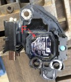
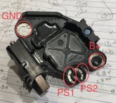
I have a Yanmar 3YM30 with the 120A Valeo alternator and I am installing a lifepo4 bank. I plan to use a Balmar mc-612 regulator. So I am attempting to convert the alternator for external regulation. Unfortunately, this alternator has a combined regulator + brush holder, which makes the conversion challenging. I know Balmar sell a replacement assembly for this very purpose! But the $200 price is off putting. Looking at the Valeo regulator, I see I could solder my own field wire to the brush holder and wire that to the external regulator, but I need to disable the Valeo regulator.

Does anyone know what the ps1 and ps2 pads are? They both seem to conduct to the W (waveform/tach) tap on the alternator. I think this is where the alternator is getting ignition/excite signal, and if so, these would be the pads I need to block.

Actually I might just look at putting insulating washers under all the pads except GND. maybe mica/ceramic? Or maybe take a Dremel and destructively remove those pads from the regulator.

thoughts?
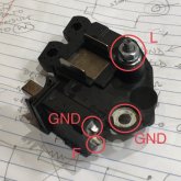
1585494831535.jpeg


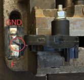
1585494995276.jpeg
 
If you can isolate the F brush from the regulator then that's all you need to do. Add a wire to it and you can use an external regulator between this wire and GND ;)
 
If you can isolate the F brush from the regulator then that's all you need to do. Add a wire to it and you can use an external regulator between this wire and GND ;)
Unfortunately, where the F brush is soldered on the back of the brush holder is a trace that leads into the internal regulator. So separating the F brush from the internal regulator is not easy to do without getting destructive. I may need to just bite that bullet!

B+ is always on and the internal regulator must be using that for batt voltage sense.
L (light) is energized though the ignition switch and has an alternator trouble light at the engine panel. This might be providing initial excite current to the internal regulator - and field.
Ps1 and Ps2... I'm not familiar with that nomenclature. They seem to be both connected to the center of the rectifier. I suspect the internal regulator gets power from here once the alternator spools up and starts generating power. And that point it stops using power the L tap.

Humm.
 
Yep, you need to be destructive but you can be only at a place who is easy to repair if needed.
 
I popped the cover off the integrated regulator. It is held in place with RTV silicone - so not hard to pull off. This reveals the traces/pads and the regulator IC. There are fine wires connecting the traces to the IC. so it is possible to isolate the field brush here by snipping the appropriate fine wire.

1585520766505.jpeg

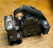
I however chose to cut the trace at the back of the brush holder. I used a Dremel and cutoff wheel for this. I can now solder my field wire to the brush. I can also restore the internal regulator by bridging what I cut with solder.

1585520535860.jpeg

now, gotta get myself some silver solder.

THIS IS NOT TESTED YET. SO PROCEED AT YOUR OWN RISK IF YOU DO THE ABOVE WITH YOUR OWN ALTERNATOR.
 
Last edited:
Yeah, don't mess with the bond wires, you'll destruct everything and on top of that most of the time they aren't solderable, so if you want to repair in the future you will not able to.

The dremel cut is what I was thinking ;)

NB: double check with a DMM that the brush is now isolated, you never know if there's another connection...
 
Do yourself a favor and set "amp-manager" to cut the alt output by 40-50% and then be sure to use an alternator temp sensor as well.
 
On a related note, how can I current limit the charging circuit in my Ford truck to my 5th wheel? Or do I even need to worry about that? I've got an DIY 160Ah LiFePO4 12V "house" battery.
 
You can use a DC to DC charger that is at least 30-50% smaller than the factory alternator.
 
Do yourself a favor and set "amp-manager" to cut the alt output by 40-50% and then be sure to use an alternator temp sensor as well.
Yes, I plan on using the Balmar amp/belt manager to derate the alternator 50%. Start there.
 
Yes, I plan on using the Balmar amp/belt manager to derate the alternator 50%. Start there.
That's a good plan, these are pretty light duty alts. You can also invest in a cylinder head temp monitor for motorcycles. It will hold the peak alternator temp in memory. You can use this to set amp manager to not exceed about 230F.
 
Spend 100.00 and have a alternator shop do it. That's what I did.
 
I have a MasterVolt Alpha Pro II regulator so I can't have one of the field wires grounded. So I made a cut like this.
Will solder wires to both posts and epoxi the cut. Question is whether to disconnect B+ and W too?

IMG_3795.jpeg
 
I have a Yanmar 3YM30 with the 120A Valeo alternator and I am installing a lifepo4 bank. I plan to use a Balmar mc-612 regulator. So I am attempting to convert the alternator for external regulation. Unfortunately, this alternator has a combined regulator + brush holder, which makes the conversion challenging. I know Balmar sell a replacement assembly for this very purpose! But the $200 price is off putting. Looking at the Valeo regulator, I see I could solder my own field wire to the brush holder and wire that to the external regulator, but I need to disable the Valeo regulator.

Does anyone know what the ps1 and ps2 pads are? They both seem to conduct to the W (waveform/tach) tap on the alternator. I think this is where the alternator is getting ignition/excite signal, and if so, these would be the pads I need to block.

Actually I might just look at putting insulating washers under all the pads except GND. maybe mica/ceramic? Or maybe take a Dremel and destructively remove those pads from the regulator.

thoughts?
View attachment 9871


View attachment 9872
PS1 and PS2 are both W.
 
Back
Top