diy solar

diy solar

LiFePO4 direct to alternator

ehahn

New Member
Joined
Aug 10, 2023
Messages
10
Location
North Carolina
Assumptions:
I understand LiFePO4 has a low internal resistance, so when you hook it up to an internally regulated alternator, the voltage differential from the battery and alternator divided by the battery’s low internal resistance causes a massive spike in current. The alternator quickly reaches max output and the alternator voltage drops such that ohms law is satisfied for the charging circuit. With a large enough battery bank, the input current isn’t a big deal for the LiFePO4. However, running the alternator at max output can cause the alternator to overheat, therefore we need a way to drop its output voltage and therefore output power to keep it from overheating (a classical duty of an external regulator). As long as you can keep it from overheating, you can continue to charge albeit at a limp output, but so far all seems well. The alternator will produce all it can until the battery pack is charged enough to allow the alternator to hit its max regulated voltage, at which point the voltage differential between the alternator and the battery will begin to decrease and therefore the circuit current will begin to decrease as the LiFePO4 continues to complete its constant voltage charge stage. As long as the BMS has overcharge protection, the battery will accept charge until full.

Question:
What am I missing? It seems with all the parameters correctly configured, the only thing I need to charge LiFePO4 off of an alternator is a way to regulate alternator temperature?

Another question. Is it possible that the BMS gets confused about when to deny charge when the battery is charging at the same time it’s under load? How does the BMS prevent overcharging? Does it disconnect the circuit completely, or maybe insert a diode into the circuit such that the battery can only discharge until the circuit voltage drops below the battery open circuit voltage?

Why ask?
Because I discovered a company claiming to make alternators with internal regulators that also are smart enough to regulate temperature


And I’m wondering if I can cut a lot of complexity and cost out of converting an alternator to external regulation, wiring up an external regulator, current shunts, SOC measurement, temperature sensors, meh - I hope I can just drop this thing in.
 
Last edited:
What am I missing? It seems with all the parameters correctly configured, the only thing I need to charge LiFePO4 off of an alternator is a way to regulate alternator temperature?
Alternators are generally considered current sources; by using a regulator (internal or external) we can adjust the current to match charging requirements.

This gets us in trouble if for some reason the output of the alternator goes open circuit.

With lead-acid batteries, this is no problem, because the battery is directly connected to the alternator; if a cell becomes full, it simply boils a bit of electrolyte off.

Contrary, LiFePO4 batteries cannot just boil off electrolyte; overcharging destroys the cells permanently. As a result, we add a BMS that can interrupt the circuit should any of the parameters. This solves about 5 problems in terms of damaging the cell, but now has created an open-circuit situation for the alternator. The voltage will spike, often times quite high, and this voltage spike can cause damage to electronics on the 12v system as well as to the BMS (depending on BMS type).

The solution to this is the external regulator that connects into the BMS (often via CANbus). The BMS monitors cell voltages and sends a pre-alarm to the alternator regulator to slow down charging long before the point where the BMS needs to trip (go open-circuit) to protect the cells.

Another question. Is it possible that the BMS gets confused about when to deny charge when the battery is charging at the same time it’s under load?
No; a battery can only be in one state at a time. Any loads during charging are powered directly from the charge source and the rest of the charge current sent to the battery.

How does the BMS prevent overcharging? Does it disconnect the circuit completely, or maybe insert a diode into the circuit such that the battery can only discharge until the circuit voltage drops below the battery open circuit voltage?
MOSFETs; see this: https://diysolarforum.com/threads/b... the discharge,again automatically by the BMS.
 
The dual alternators in my Ford F-350 are fairly smart. When one gets too hot, the other takes over, letting the first one cool down. Ford markets the charging system as 397 amps. Reality is that the system would not produce that much.

To keep from burning out the alternator, many forum members are using a DC-DC charger. The charger outputs only so many amps, which protects the alternator from being overloaded.
 
The assumption that the regulator limits the amps could be wrong. Most alternators will run flat out to hold voltage at the regulated voltage regardless of amps and will overload. Generally the alternator will be sized larger than the full load to avoid the issue. Enter an LFP battery and overload is easy.

DC-DC charger is common to limit the amps and correct the voltage to match charging specs.

Best to contact dcpower inc with your specific situation. Might work just fine. I still don't like the idea of running equipment up against a high temperature limit on a regular basis. Best reserved for extraordinary circumstances. And again these concerns should be addressed with the builder and how the situation will affect the warranty.
 
Our setup:
The "non smart" original 100A rated alternator in our Mitsubishi Canter 3.9l turbo diesel truck based motorhome has survived 9 years of full-time travel direct charging the 4 cell 300Ah LiFePO4 Sinopoly battery at 70-80A without releasing any smoke yet.
No standard "BMS" circuitry involved.
I recently paralleled a 4 cell 280Ah LiFePO4 EVE battery.
As well as powering our house it has also started the truck perhaps a few thousand times over the years. Perfect performance so far.
The "BMS" involves no charging source exceeding 14.1V at which point the battery is always at 100% SOC regardless of charge current. 80A alternator, 50A solar and 30 battery charger.
20% SOC alarm and Victron BatteryProtect disconnect at 12.5V. Never triggered.

I'm guessing that the alternator must have some form of temperature control?
Charge current starts at c95A and drops to nearer 70A over about 30 minutes.
 
Contrary, LiFePO4 batteries cannot just boil off electrolyte; overcharging destroys the cells permanently. As a result, we add a BMS that can interrupt the circuit should any of the parameters. This solves about 5 problems in terms of damaging the cell, but now has created an open-circuit situation for the alternator. The voltage will spike, often times quite high, and this voltage spike can cause damage to electronics on the 12v system as well as to the BMS (depending on BMS type).

Thanks for the solid write up! This is a good point.

I gather this is because the internal regulator is too slow to respond to the rapid change in demand, causing voltage to spike when the battery is disconnected.

Note: I plan to always have a load attached, so even if the battery BMS suddenly disconnects, it will never be truly open circuit.

I can think of two solutions:

  1. Dc surge protector (do they even make these?) plus maybe a 12v capacitor to keep things alive while the alternator recovers (or will the LiFePO4 BMS come back online quickly enough while the surge protector has the circuit broken so as to not need a capacitor? And will it turn back off immediately once the surge protector restores power?) I suppose it’s possible this could result in a feedback loop if we’re not careful though.
  2. Ensure charge voltage is at a peak when the battery is at peak voltage so the BMS will never have to shut off suddenly. This isn’t ideal and will result in only getting to about 90% SOC but I think I’d rather spend money on another battery than I had spend it on external regulators. I think I can use resistors to drop the voltage maybe 0.4ish volts if necessary? The line losses may be enough without resistors to get an effective 14.4 charge voltage.
 
Last edited:
The "BMS" involves no charging source exceeding 14.1V at which point the battery is always at 100% SOC regardless of charge current. 80A alternator, 50A solar and 30 battery charger.
20% SOC alarm and Victron BatteryProtect disconnect at 12.5V. Never triggered.
Genius! I thought of that right before I saw your post. Great to know it’s working out for you! Sounds like I might be following in your footsteps! Hopefully with a larger charge current in the constant current cycle though.

I'm guessing that the alternator must have some form of temperature control?
I emailed them asking about it. I’ll have to wait until Monday to see what they say. I hope it does! Although if it’s been working fine for you for so long without any type of thermal regulation I might just have to try it anyway!
 
If you are really interested in alternator charging, check out what the marine guys are doing. There are a number of examples of what to do and what not to do out of those forums.

If you are really interested in small frame alternators, then you should check out Balmar and and what they offer. https://balmar.net/alternators/

You will need some sort of protection device to absorb the surge when the LFP pack disconnects, otherwise you will blow out the regulator in short order.
What about something which interrupts the field circuit on the alternator? Like a relay which is normally held closed, but opens when the bms disconnects the battery. opening the field circuit.
 
I wouldn't use an alternator unless it used an external regulator or I pulled the one it had out. Not too hard to set a fixed voltage and current for someone like me. Just fool it into thinking the voltage is too high when it sees high current exactly like is done with buck converter
 
You will need some sort of protection device to absorb the surge when the LFP pack disconnects, otherwise you will blow out the regulator in short order.
What about something which interrupts the field circuit on the alternator? Like a relay which is normally held closed, but opens when the bms disconnects the battery. opening the field circuit.
Hmm, yeah sounds like the easier path would be to rate the alternator output voltage such that the BMS never disconnects. I'm ok with 90% SOC.
 
Hmm, yeah sounds like the easier path would be to rate the alternator output voltage such that the BMS never disconnects. I'm ok with 90% SOC.
What about if your battery gets too cold and you trigger low-temp protection?
 
What about if your battery gets too cold and you trigger low-temp protection?
Another good point! This rapid load demand change problem is getting pretty pesky. I still question though, are we certain it's easier to control for all possible causes than it is to mitigate? How about a voltage sensing device that diverts to a dimmable load that ramps down slowly? Is PWM possible on a relay as large as 500 amps?

Before I go digging into that, is there any quantitate evidence laying around about what exactly happens when load demand rapidly changes like this? How high does the dc output voltage spike? And how long does it take the internal regulator to pull the voltage back down?

As a side note, I found a data sheet on an Infineon automatic voltage regulator (AVR) and it mentions having a High Voltage Excitation Off (HEO) feature. So at the very least, the high voltage spikes seem to be on the radar of the AVR manufacturers. Barring evidence and for the sake of the everyone wondering if we can actually cut some complexity out of the alternator charging problem, I question whether a rapid load change event would actually fry one.
 
I still question though, are we certain it's easier to control for all possible causes than it is to mitigate?
How about if the BMS's MCU glitches out and randomly shuts down? Most external regulators controlled by CANBus immediately stops charging when signal from the BMS is lost.

I question whether a rapid load change event would actually fry one.
Absolutely - there are threads on this forum to show it. ABYC requirements require pre-alarm for batteries with a BMS on boats. Quick search here on the forum should reveal a few threads.


Is it better to treat the cause or the symptoms? Looks like you're searching to treat the symptoms, when there are already well established treatments for the cause. Just my opinion - worth as much as ya paid for it.
 
Question:
What am I missing? It seems with all the parameters correctly configured, the only thing I need to charge LiFePO4 off of an alternator is a way to regulate alternator temperature?

An alternator has a duty cycle.

As such, it can not run at full output all the time.
 
How about if the BMS's MCU glitches out and randomly shuts down? Most external regulators controlled by CANBus immediately stops charging when signal from the BMS is lost.
My application is for overlanding, so I can absorb a little more risk than a yacht could. This seems unlikely, but in this case I'd probably buy another LiFePO4 with the BMS.

Absolutely - there are threads on this forum to show it.
Most of the ones I was able to find mention frying the alternator due to it getting too hot, but I haven't seen anything mentioning frying the internal regulator due to a voltage spike. Given that the job of the internal regulator is to adjust the voltage output of the alternator irrespective of changing load conditions, it would seem that the BMS disconnecting is just another load condition change indistinguishable from other high-load change events such as releasing the winch button on a high-amp-draw winch. If the internal regulator fails to regulate the voltage, isn't it just failing at it's job entirely? This seems like a "you had one job" scenario lol

In the case that the rapid load change does fry the internal AVR, what mitigations might we have at our disposal? My goal is to dig as deep as I can here and tease out the simplest and cheapest solution that covers 99% of use cases.

I imagine a large enough capacitor would work to smooth out this voltage spike. The only question is how large would it have to be to do so?

I appreciate all the feedback guys - I know I'm running against conventional solutions here.
 
I imagine a large enough capacitor would work to smooth out this voltage spike. The only question is how large would it have to be to do so?
If that is impractical, rather than adding a large capacitor in parallel, perhaps I could use a zener diode, resistor, MOSFET, and 500A relay to divert current to an empty capacitor to absorb the load when voltages exceed the zener diode threshold. A capacitor's charging curve is logarithmic, so this seems like the perfect solution to slowly bring down the current demand while the AVR adjusts. Then I'll just add a light or something to the capacitor to drain it down for the next voltage surge event.
 
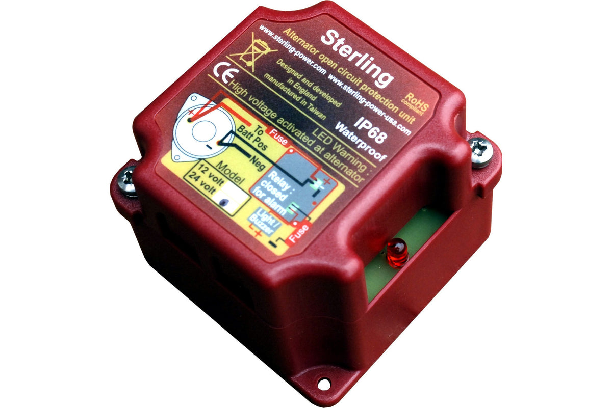
Balmar makes alternator protection devices for this purpose.
I have my large alternator (now 400 amp) connected to the lead acid starting bank, then use a combiner relay to join the house LFP bank. So the LCA takes any surge disconnects from the the system.
 
My goal is to dig as deep as I can here and tease out the simplest and cheapest solution that covers 99% of use cases.
Battery to battery chargers were designed to solve the issues under discussion. Apart from protecting the alternator they control the charge process, setting a charge current and absorbtion period. An alternator used direct cannot terminate the charge when the battery is 'full'.
It's possible to design a circuit that can deal with load disconnect on alternator, or you can buy one,
Even using such circuits does not prevent the 'stuff' connected to the 12v system receiving a momentary higher than normal voltage, perhaps damaging vehicle electrics.
Attempting to controll the alternator output volts to deal with a load disconnect is a challenge. The stored magnetic and inertial energy in the rotor, perhaps rotating at 7000 rpm, has to go somewhere!
 
It's possible to design a circuit that can deal with load disconnect on alternator, or you can buy one,
Beautiful! You don’t need a capacitor because it only diverts current to circuit ground if voltage exceeds 18v, and if voltage exceeds 18v you can be sure your internal regulator is in the process of reducing current to the field excitation circuit. I’ll probably just buy one of those. Thanks for sharing!

Now as long as my BMS prevents overcharging, my alternator prevents overheating, and this device prevents voltage spikes, it seems I’m good to go! If you guys can’t think of anything else likely to go wrong, I think I’ll give it a go and report back.
 
Back
Top