New member, looking for possible answers...Living off-grid in Panama...Does anyone have info on hacking 18 vdc cordless tools to operate off a 24vdc battery bank. I have seen things you can buy to put on the bottom of tool to be able to attach batteries of different voltages...But I don't want to spend $'s... I want to hard wire 18vdc cordless tools that someone gifted me becasue their batteries went dead and they didn't want to buy expensive new batteries....So, does any body have some comments about how to hard-wire 24 volt bank to 18vdc cordless tools. Would have to probably be some sort of resistor set-up to reduce 24-26 vdc to 18vdc. Thanks.


You are using an out of date browser. It may not display this or other websites correctly.
You should upgrade or use an alternative browser.
You should upgrade or use an alternative browser.
Cordless tool hack
- Thread starter JPW
- Start date
I have no input, but this is a cool idea, curious to see where the conversation leads!
svetz
Works in theory! Practice? That's something else
300 W / 18V = 17ASeveral different tools...200-300 watts...People are always giving away these things when their batteries crap out...Be great to be able to adjust the 24vdc to voltage for particular freebie tool...They range from 12-20vdc.
3 of these in parallel? 9V looks more common., possibly less expensive... some sort of 2SxP?
Hedges
I See Electromagnetic Fields!
- Joined
- Mar 28, 2020
- Messages
- 20,808
I suppose you have a large battery bank for your house, large compared to the power you plan to draw with these tools.
6x4 = 24V
6x3 = 18V
If your battery has taps between cells, could run the tool off 18V. Be sure to use a suitable fuse.
How well does your charging system handle imbalance between cells?
Lead-Acid gets an equalization charge, bubble the fully charged cells while bringing the undercharged ones up to voltage.
Lithium has a BMS which might provide balancing.
If you needed 12V out of a 24V bank or 18V out of 36V, I'd say charge a set of batteries in series, then connect them in parallel to get the lower voltage. You could try running all the tools at 12V; the 18V would run slow.
You could keep the 24V setup for your house, run the tool off the lower 12V for a while, then off the upper 12V to equalize discharge.
Hedges
I See Electromagnetic Fields!
- Joined
- Mar 28, 2020
- Messages
- 20,808
These 18V regulators are 27W each, so 14 in parallel for 378W at $5.44?
Looks like you got 27W = 18V x 1.5A
How well does the output current balance if you try to parallel them? Maybe need a resistor on each to help balance?
Max junction temperature 125C, let's shoot for 110C to maintain some margin.
Assume 40C ambient? (I usually try to make things work at 85C.)
110C - 40C = 70C temperature rise
Theta J-C = 5 degrees C/watt
Theta J-A = 60 degrees C/watt (if no heatsink)
Power dissipation is nominally (24V - 18V) x 1.5A, 9W each. Let's use (28V - 18V) x 1.5A = 15W
With no heatsink, 70C/60C = 1.17 so only 1.17W not 15W without overheating, need 12.8 times as many. 12.8 x 14 = 179 regulators needed.
With an infinite heatsink kept at 40C, 70C/5C = 14W. 15W/14W = 1.07; 1.07 x 14 = 15
So it could be done with 15 regulators in parallel if current perfectly balanced between them, heatsink limited to 40C, while keeping junction no higher than 110C for good life. Large heatsink and a fan could do it, or water cooled.
Don't even try to boost output current with MOSFETs. Their Safe Operating Area for DC doesn't come anywhere near the SOA in the datasheet (local thermal runaway of transistors in the die.) Bipolar transistor as source-follower after a regulator could work better.
I found a transistor which looks like it could work, but I don't think you'll like the price:
JANTXV2N5686 Microchip Technology | Discrete Semiconductor Products | DigiKey
Order today, ships today. JANTXV2N5686 – Bipolar (BJT) Transistor NPN 80 V 50 A - 300 W Through Hole TO-3 from Microchip Technology. Pricing and Availability on millions of electronic components from Digi-Key Electronics.
Here's a more affordable one but only rated 15A. Could parallel two with an "emitter degeneration resistor" to balance them:
2SC6145 Sanken | Discrete Semiconductor Products | DigiKey
Order today, ships today. 2SC6145 – Bipolar (BJT) Transistor NPN 230 V 15 A 60MHz 160 W Through Hole TO-3P from Sanken. Pricing and Availability on millions of electronic components from Digi-Key Electronics.
Five of these resistors in parallel for 5W, 0.164 ohms:
RSF100JB-73-0R82 YAGEO | Resistors | DigiKey
Order today, ships today. RSF100JB-73-0R82 – 820 mOhms ±5% 1W Through Hole Resistor Axial Flame Proof, Safety Metal Oxide Film from YAGEO. Pricing and Availability on millions of electronic components from Digi-Key Electronics.
One 18V regulator, two 15A NPN transistors, two resistors of about 0.17 ohms 5W could work.
The transistors have 0.78W theta J-C, 56 degree rise when 17A split as 8.5A each.
These transistors rated 150C, operate at 125C junction or below for margin, OK for heatsink up to 68C.
Looks like about $10 worth of parts plus shipping (which would be about $7 in the US for priority mail, might go first class overseas.)
Heatsink and fan not included, left as an exercise for the reader.
svetz
Works in theory! Practice? That's something else
Great analysis!... left as an exercise for the reader...
This would probably be an interesting experiment, I'd certainly follow the project. If you dive into it, don't expect it to work the first few times and you'll probably spend a lot more than $10 before you finally get it working.
svetz
Works in theory! Practice? That's something else
You could do that on the PCB by keeping the input traces from the source to the regulator and all the same length right? Something like:... if current perfectly balanced between them...

Hedges
I See Electromagnetic Fields!
- Joined
- Mar 28, 2020
- Messages
- 20,808
You could do that on the PCB by keeping the input traces from the source to the regulator and all the same length right? Something like:
Only if long enough to swamp out resistance of the transistors.
Matched length and width, or matched "squares" (ratio Length/Width) would match trace resistance so the traces don't cause imbalance.
In the case of MOSFETs they have an "on" resistance which may balance the current fairly well. Although, they can get into thermal runaway.
But for Bipolar it might not be enough. Using the following calculator I came up with 32" of 100 mil wide, 1 oz copper at 40 degree C to hit my target (SWAG) of 0.165 ohms:
Trace Resistance Calculator - Electrical Engineering & Electronics Tools
This calculator determines the resistance of a microstrip trace
 www.allaboutcircuits.com
This table indicates my guess of 100 mil was low, ought to be 200 mil (so make that 64" long trace). Resistors are cheaper than PCB. Could use a length of wire instead, I suppose.
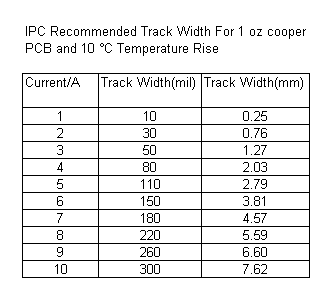
PCB Trace Width Calculator | Trace Width Vs. Current Table
Learn more about how to calculate trace width and current PCB carrying capacity from MCL - your source for printed circuit boards.
 www.mclpcb.com
Bipolar transistors have gain (collector current/base current) which might start fairly well matched, but increases with temperature and can run away.
Base current is an exponential function of voltage and will differ somewhat between parts. Having a resistor on the base can dominate so at least base current is matched. Emitter degeneration resistor provides negative feedback: Higher current in one transistor results in higher IR drop, raising voltage of collector slightly. Doesn't take much to reduce Vbe and therefore collector current of that transistor.
This burns some power but makes the circuit more stable and reliable.
I've also used PTC thermisters in bias circuit (thermally intimate with the transistor heatsink) to reduce gain when hot. It worked pretty well both in SPICE and with my heatgun thermal test.
When I paralled two Sunny Island (my picture) I had 40' of 6 AWG on the input and 20' on the output. I expected that resistance to keep the pass-through current balanced (they each have a max current allowed through a relay.) But they were imbalanced something like 3:1. Turned out the 70A Square-D QO breakers I put on output differed enough in contact resistance to cause that. Other models/brands on the input were not a problem.
(You can just imagine what goes into a well designed inverter, and what doesn't go into those cheapies we've seen videos of failing.)
svetz
Works in theory! Practice? That's something else
https://www.dewalt.com/products/acc...ax-battery-adapter-kit-for-18v-tools/dca2203c ... wonder if the input side could tolerate 24V?
svetz
Works in theory! Practice? That's something else
| Lithium Ion is 3.6Vnom, so an 18V pack would have 5s?p cells. So, 18V tools must work in the range of 4V x 5 to 3.4V x 5, or 20 to 17V. That got me to thinking, we really only need to go from 24V to 20V... so how about 4 diodes in series? For example, this one is a $2.07/ea and has a 1.1V forward bias at 20 amps, so that would be a 4.4V drop or 19.6V. | 
|
Last edited:
I was thinking the same thing.
Lithium Ion is 3.6Vnom, so an 18V pack would have 5s?p cells. So, 18V tools must work in the range of 4V x 5 to 3.4V x 5, or 20 to 17V.
That got me to thinking, we really only need to go from 24V to 20V... so how about 4 diodes in series?
For example, this one is a $2.07/ea and has a 1.1V forward bias at 20 amps, so that would be a 4.4V drop or 19.6V.
5s LMC cells charge at 4.2V per cell, and operate at nominal 3.7V, or 18.5V to 21V...so, charging needs to be 21V.
many CC/CV rapid chargers operate at 24V, WITH CELL CHARGE MONITORING TEMP OF EVERY BATTERY...
So, not for the diy crowd... but if the packs have the monitoring and you have the original charger, it could be modified with some Pi programming...
Hedges
I See Electromagnetic Fields!
- Joined
- Mar 28, 2020
- Messages
- 20,808
That got me to thinking, we really only need to go from 24V to 20V... so how about 4 diodes in series?
What is the maximum voltage expected from a "24V" battery bank?
Could be undergoing charging even while he's using it, maybe even equalizing. Assume 30V? or at least 28V?
28 - 20 = 8V.
You selected a bridge rectifier, four diodes with two in series that could be used.
1.1V drop (per diode) at 20A, but 0.7V at 1.0A (even less under no load).
If the tool has a variable speed control, it's electronics will be exposed to the full battery voltage, but operating the motor will drop voltage.
Dropping 8V with pairs of 1.1V diodes takes 3.6 pairs. Either use 4 pairs or 3 pairs and one single.
At 17A, voltage drop will be near full 2.2V for 37W.
Data sheet says R theta J-C 4.75 degree C/W with 4 x 5 x 0.25" aluminum plate heatsink.
(Think they meant to say R theta J-A, junction to Ambient, rather than junction to case.)
37 x 4.75 = 175 degree C rise.
Maximum operating temperature 150 degree C junction.
That would be reached with -25 degree C ambient.
It ought to be operated about 25 degrees cooler than max rating for better lifespan.
Sizing heatsink twice what the data sheet suggests so only 90 degree rise allows 35C ambient and 125C operation.
90/(37 x 4) = 0.61 degrees C/W desired performance
Here's a heatsink rated 0.56 degrees C/watt with natural convection:
510-3U Wakefield-Vette | Fans, Thermal Management | DigiKey
Order today, ships today. 510-3U – Heat Sink Power Modules Aluminum - Top Mount from Wakefield-Vette. Pricing and Availability on millions of electronic components from Digi-Key Electronics.
Substitute a suitably large scrap of sheet aluminum to avoid the cost.
Make that an aluminum frying pan and you can cook breakfast at the same time. It'll fry an egg.

Ampster
Renewable Energy Hobbyist
I have consistently over volted my ebike motors from original 36 volts to 48 volts. It is possible your tools can work on 24 volts.
Similar threads
- Replies
- 0
- Views
- 204