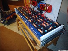
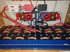
Just finished a 16s2p 580ah EVE LF280K battery pack. It will be powering a Growatt 12kW Split Phase Off-Grid Inverter. The battery pack has been lightly tested and everything seems to be working as it should. I have 2x 160a DC circuit breakers on each positive lead (that also act as my main battery disconnects) and will still be installing a 300a Class-T Fuse on the main 4/0 gauge battery cable before the inverter. All cables are 2/0 gauge before the main bus bars and I will be using 4/0 from those to the inverter. I oversized everything, including 500a Daly BMS's and all components are attached to cement board. The smaller bus bars are rated for 300a and the larger main bus bars are rated for 500a. Before I put this unit into full operation, I would like some feedback. I've attached a few pictures. Does anyone see any long-term issues with this setup? I do plan to construct a cover to place on top of the battery pack to protect the components. Cheers.


You are using an out of date browser. It may not display this or other websites correctly.
You should upgrade or use an alternative browser.
You should upgrade or use an alternative browser.
Critique my Battery Pack - 16s2p 580ah EVE LF280K
- Thread starter mlebs
- Start date
sunshine_eggo
Happy Breffast!
Looks pretty good. What's between the cells?
Nothing.....yet. Still debating this.Looks pretty good. What's between the cells?
If you decide you want to insert separators, make sure you do it at a low state of charge and the cells are cool to greatly reduce any swelling. I got a roll of white Formica (no carbon coloring) and skived a line with a utility knife and straight edge. I cut hook into the utility knife blade with a cutoff wheel. If you do it right you can snap it off. I use an orbital sander to smooth the texture of the glue side. Or you can just buy what I couldn’t find at the time. https://www.18650batterystore.com/p...or-sheet-208-175-0-5mm-lifepo4-cell-separator


featherlite
Solar Enthusiast
Would it be better to install class T fuses between the two breakers and the pos posts of the batteries, as close to the battery posts as possible?
Watch the Dalys like hawk, it’s not that they don’t have the current capacity, they handle that easily. I’ve found that the logic just stops doing a feature. Sometimes an update will fix it and other times it’ll brick it. At least you have redundancy.
Thanks for the tip!If you decide you want to insert separators, make sure you do it at a low state of charge and the cells are cool to greatly reduce any swelling. I got a roll of white Formica (no carbon coloring) and skived a line with a utility knife and straight edge. I cut hook into the utility knife blade with a cutoff wheel. If you do it right you can snap it off. I use an orbital sander to smooth the texture of the glue side. Or you can just buy what I couldn’t find at the time. https://www.18650batterystore.com/p...or-sheet-208-175-0-5mm-lifepo4-cell-separator
View attachment 168858View attachment 168859View attachment 168860
featherlite
Solar Enthusiast
There are very many knowledgeable people who confirm that the fuse should be as close to the battery as possible.Placement near the battery post is not important.
The ABYC requirement for a battery bank fuse is that the fuse must be within 7 wire inches of the battery bank.
There are many posts on this forum confirming this truism. For example, see one of this forum's moderator's posts at this link:
https://diysolarforum.com/threads/which-goes-first-fuse-or-switch.27070/
hardtop
New Member
Looking good. Thick gauge positive wires. What size are they? Those DALYs remind me of a video card lol.
Marinepower
Solar Enthusiast
- Joined
- Apr 24, 2020
- Messages
- 224
Looks good to me.
You will have to fuse everything for the smallest wire, which looks to be the gauge of the pos and neg wire coming out of the two upper boxes. I cant tell if these are bussbars or fuse boxes?. Looks like 2awg or 1 awg coming off of these, so around 175 - 200 amp fuse that can handle 52 volts.
Also, heat shrink on these connectors will stave off long term corrosion issues with un-tinned copper.
Where did you source the lower bussbars? Those look compact and the covers are tidy. I want some for my project....
MP
Marinepower
Solar Enthusiast
- Joined
- Apr 24, 2020
- Messages
- 224
I think I found the busbars on amazon. https://www.amazon.ca/Terminal-Distribution-Boating-Fishing-Switches/dp/B095164Y65?th=1
Note these are brass and not copper bus bars and brass is 1/3 to 1/4 the conductivity of copper. Should not be a problem depending on how thick / wide they are ...
Note these are brass and not copper bus bars and brass is 1/3 to 1/4 the conductivity of copper. Should not be a problem depending on how thick / wide they are ...
?I think I found the busbars on amazon. https://www.amazon.ca/Terminal-Distribution-Boating-Fishing-Switches/dp/B095164Y65?th=1
Note these are brass and not copper bus bars and brass is 1/3 to 1/4 the conductivity of copper. Should not be a problem depending on how thick / wide they are ...
Marinepower
Solar Enthusiast
- Joined
- Apr 24, 2020
- Messages
- 224
This Bluesea Sytems is my fav, budget buss bar. A huge piece of copper..
 www.fisheriessupply.com
Blue Sea Systems 2127 | Fisheries Supply
Save More on Your Blue Sea Systems #2127 MAXIBUS 4 X 5/16-18 STUDS at Fisheries Supply. Excellent Customer Service, Ready to Ship. Marine Supplies Since 1928!
www.fisheriessupply.com
Similar threads
- Replies
- 23
- Views
- 1K
- Replies
- 0
- Views
- 241
- Replies
- 53
- Views
- 2K