diy solar

diy solar

What determines your battery-inverter bus bar size?

It has been noted on the forum by a few that you can 'double stack' the ring terminals, if you need to. I prefer to use a long enough bus, that each inverter has it's own stud. If you ever need to do work on the system, you can remove a single cable without affecting other units if they are each on separate studs.

Stacking ring terminals is bad in general and only if you MUST do it would I. If you do it, don't stack more than two together and put the highest current draw next to the bus bar. I am asssssuming that the one in Will's video that looks double stacked is actually one on the front and one on the back of the bar.
So maybe these and I’m good?
Or these for a bit more with a plastic cover…too bad I can’t find a six stud.
Either of these would be great. I would get the 8 stud version in case you ever decide to expand. Solar is addictive.
What is your logic going from 4/0 to 2/0? Is the length of 2/0 very short? It's seemed from one post that this was a situation of one battery and two inverters? If so, that would be an explanation.

It is, one battery bank and two inverters setup as split phase from what I can tell.
For me would I do
Inv1-inv2-battery-inv3-inv4


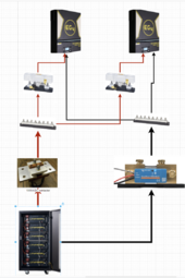
I would use something like the attached initially and you can add an extra pair of inverters to the side of each of the existing ones. Heavy lines are 4/0 and lighter lines are 2/0. The contactor acts as a switch to turn off the battery. You do need the rest of the parts for it, basically a small switch to activate it, power that isn't connected to the battery, and wiring of the appropriate size. Something like 18awg generally. I went with a contactor verse breaker because I knew it would handle the current and if you are just doing a switch why have a breaker. Also if you grid tie you can use an external switch as the cutoff for the battery bank.

Buy good wire, pure copper welding wire. Windy nation is good and I have also bought wire from shirby. For this application the finer stranded the better and high strand count is great. There are other reputable vendors but a lot will sell copper clad aluminum (CCA) which doesn't have nearly as high a current capacity.

Also make sure you have a good crimper for this, if you want to grid tie it must have the awg number imprinted into the lug when you crimp it. I personally favor the Temco hydraulic crimper. There are others that work as well.


And when you crimp the correct size wire in the correct size lug with the correct size crimper it comes out beautifully. If you crimp and there are wings sticking out something is not the correct size.

Quality lugs cost - get Temco or Ancor --
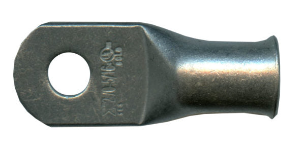
OR just figure out the size cables you need and length and lug endsfor each and windy nation will make them to order. When I was pricing things I figured out my break even was about 6 cables made.

Make sure to read the specs on the breakers and the curves for your voltage to see how many DC amps it will take to trip it. There are a number of examples in the 'up in smoke' where the breakers never tripped dispite home built battery meltdown and resulting fire. They are good switches but not so good at tripping
 

Attachments

  • simple setup.png
    simple setup.png
    372.8 KB · Views: 7
Last edited:
4/0 wire carries current for all inverters. 2/0 for one inverter.
But it reads as though each battery gets a larger cable than the cable from the bus (where all the batteries are combined) to the inverter. Wouldn’t ideal be the opposite since theoretically each battery has less energy demand than from bus to inverter
Edit: I see that it’s 2 inverters now.
Sigh. I can’t read for sh*t today
I see you woke up like me this morning - I'm almost fully conscious now ;)
 
I decided on two of these:
1000a each with cover for $138 each shipped and sold from amazon...they better not be fakes.

2/0 from inv to nader, 2/0 from nader to bus (for + here), 4/0 from bus to rack...later if add second rack, 4/0 from rack to bus...this should cover it...hopefully
Personally I really prefer the Victron Lynx Power In. 2x1000amp bus bars in a single enclosure with very good protection. Takes up less space on the wall, too ;)
 
Personally I really prefer the Victron Lynx Power In. 2x1000amp bus bars in a single enclosure with very good protection. Takes up less space on the wall, too ;)
And then one can simply add a second power in when they occupy the lugs of the first one.
Such a clean system design
 
Personally I really prefer the Victron Lynx Power In. 2x1000amp bus bars in a single enclosure with very good protection. Takes up less space on the wall, too ;)
Since I'm running 4 inverters, not sure how I could stagger and get equality of current with this? I do like how it's setup tho.
 
Here is with 4 inverters, sorry, it is just scratchpad without being neat.... I spend hours sometimes moving the lines around.


simple 2.png
 
Here is the drawio file if you want to play with the wires. Have to put it in a zip file or the extension gets rejected.

If you want to add labels - I figured put in 250 amp class T fuses at close to the bus bars as possible and make things neat. This protects the 2/0 wire and lets more than the needed current through. Fuses are to protect wires not equipment. Might even take it to 300ap so it only blows in an actual short situation. Your 2/0 wires as well as the ones inside the case should be protected by the breakers in the Lifepower.

The 1000amp bus bars - lots of people are fond of the victron lynx but for the price I prefer 8 studs verse just the 4 in the lynx per unit. You can stack them and keep them pretty and it only costs a bit more. The other thing is you need some sort of cover over the bus bars

Note - if I was doing an entirely victron setup I would do lynx just to couple everything together.

The 1000a shunt is so you can keep track of everything. I chose victron because several other cheap shunts I have tried were almost 10% out when doing readings with a good clamp meter and a volt meter. your choice what you do.
 

Attachments

  • simple setup.zip
    2.9 MB · Views: 3
Last edited:
I would put one class t fuse at the rack.
I considered that except if all 4 inverters are maxed out they will draw 612 amps. The batteries are capable of putting out 600amps. So would require about a 720amp fuse to not blow when maxing out. Looking at busman fuses that can handle that they are around $400 each and the single holder I can't find.


Simpler to fuse each inverter and cheaper if the fuses blow. Especially since you want to keep a set of extra fuses on hand.

I looked at Dave's video and he only fuses to 400 amps... which means with 4 inverters you would blow the fuse long before you reached max current.
 
Last edited:
Stacking ring terminals is bad in general and only if you MUST do it would I.
Not sure why you are saying this? I assume you are referring to lugs and not those thin ring terminals used on smaller gauge wires. If so even Victron recommends stacking since the current then wouldn't need to pass through the busbar at all.
 
Not sure why you are saying this? I assume you are referring to lugs and not those thin ring terminals used on smaller gauge wires. If so even Victron recommends stacking since the current then wouldn't need to pass through the busbar at all.

Long discussions in other threads on the topic and it comes down to something like do you prefer emacs or vi?

I poked around on the victron site and I can't find anyplace where they recommend stacking lugs. I can find several examples where they explicitly say you should never do it. My search was admittedly brief so maybe you can point the way to where they recommend it?

Basically the reason I say it is because the bar is smooth and when you put a lug on it and you put the nut on it and tighten you are compressing everything to get as good a surface contact as possible. You also get the full surface of the lug in contact with the bar.

Now when you stack them the lugs are not perfectly flat and you compress them with the nut. The first one has good contact with the bar. The second one is twisted sideways a bit and only has the contact surface between the lugs so slightly smaller area. You also have more material to expand and contract so more potential for loosening the nut, more potential for corrosion and resistance between the lugs.

Will does a video where he talks about stacking lugs and shows how it can create hot spots. He comes down to recommending not to stack or to only stack 2.
 
I considered that except if all 4 inverters are maxed out they will draw 612 amps. The batteries are capable of putting out 600amps. So would require about a 720amp fuse to not blow when maxing out. Looking at busman fuses that can handle that they are around $400 each and the single holder I can't find.


Simpler to fuse each inverter and cheaper if the fuses blow. Especially since you want to keep a set of extra fuses on hand.

I looked at Dave's video and he only fuses to 400 amps... which means with 4 inverters you would blow the fuse long before you reached max current.
You are trying to protect the battery wire. Your setup doesn't do that if the short is before the fuse.
 
poked around on the victron site and I can't find anyplace where they recommend stacking lugs. I can find several examples where they explicitly say you should never do it. My search was admittedly brief so maybe you can point the way to where they recommend it?
I can't find this either.. I know I saw it somewhere and thought it was there. But it still makes logical sense to me if you have main battery cable connected to a busbar that you also connect the main load to same stud. I'm also talking about using high quality tinned copper lugs (usually non-Amazon sourced ones).
 
You are trying to protect the battery wire. Your setup doesn't do that if the short is before the fuse.
What would you suggest? The only addition I can think of would be to add 125a MRBF fuses on each battery and use the built in breaker as just a switch.

It is an imperfect world.
 
So maybe these and I’m good?
Or these for a bit more with a plastic cover…too bad I can’t find a six stud.
Just do a lynx power in, dual 1000a and clean wire management
 
Just do a lynx power in, dual 1000a and clean wire management
Why are you pushing the lynx so hard? Do you own stock? They have their place especially if you do an all blue system but the are kinda pricy for what they do. Dual 4 post bus bar that is expandable, but for his design my opinion is the blue sea bus bars are a better choice.

If I am missing something tell us why the lynx is better?
 
Back
Top