diy solar

diy solar

Just how terrible is a brass bus bar

SparkyJJO

(un)Certified Arc Generator
Joined
Jan 31, 2022
Messages
1,759
Location
Ohio
I know copper is much better. I made a mistake. I bought a bus bar set to connect two battery packs to my inverter, I thought someone here had bought this one before and said it worked well, but maybe they bought one that looked like it but this was the cheap brass knockoff. Anyhow, I bought it a long time ago.


I was stupider 2 years ago, OK? :ROFLMAO:

No, I don't have it all set up yet... thought we were moving so I held off, then we weren't, then life happened, another kid came, something else big needed fixed on the house, then we were looking for property again, then interest rates, then then etc etc... OK enough excuses. Thankfully we've had stable grid so my grid tie has been fine and we haven't need the batteries.

Anyway, I've been back on the process of setting things up. I'm on the fence between replace these before I even install, or just going with them and seeing how terrible they really are. Running an Outback Radian 8048A.

The other question is, if I replace them, I'll get something with more terminal capacity. Between the dual inputs on the inverter and two battery banks I'd fill a 4 lug bar, so if I ever add batteries (which I will if we do ever move to a different property, not doing a full out grid tie again), I'd need more space. Was thinking something like two of these : https://www.amazon.com/GOUNENGNAIL-25-Copper-Terminal-Positions-Grounding/dp/B08PYBNYKV
But being advertised as "grounding" bus bars, there's no covers. Anyone use something like this and fab your own cover somehow? I just don't want any short circuit risks, and I don't want to just slap electrical tape over it hah.

I can get a bus bar set with covers for more money, but the price is significantly higher for just adding a little more of a pretty appearance and a cover. Example: https://www.amazon.com/jamgoer-Distribution-Terminal-Battery-Automotive/dp/B0BNHST9NP
 
Brass is roughly 1/4 the conductivity of copper, so it has to be 4 times the cross section to be equivalent losses.

Mike C.
 
I have a pair of those busbars in my camper system that was built almost 4 years ago. They work fine for that 24V application, the loads never exceed 60A. Only paid about $25 each for those.

For the house system with larger inverter capacity, I used a Victron Lynx https://www.amazon.com/gp/product/B00NT9X5AG/ref=ppx_yo_dt_b_search_asin_title?ie=UTF8&psc=1 which can handle 1000A. Well worth the money and as I am adding another battery in a Luyuan box I can simply tie into the Lynx.

For my charge controllers I used the Blue Sea, also a good product. https://www.amazon.com/gp/product/B006VELFDK/ref=ppx_yo_dt_b_search_asin_title?ie=UTF8&th=1 But only rated to 250A which is perfectly fine for what I am using the busbars for.
 
Pike Industries make an honest 400A buss bar.

Otherwise, maybe you can use that Amazon one for something with less current. They say its Copper farther down in the 300A description even though they say Brass??? Maybe they are referring to a zinc/brass plating?

The above post is correct in that you may see a voltage drop along with the bar getting hot if it simply cant handle the load.
 
Brass is like 1/3 the conductivity of copper. Who knows how they decided that it was 400A rated -- is that when the buss bar is at 100 degC? We all know how "optimistic" vendors on amazon can be sometimes... Having said that, unless you're actually pushing close to that rating, it's probably fine.

I would try and generate the maximum current you can in your situation (both charge and discharge), and measure the voltage drop from lug to lug. Based on that, you can figure out how many watts are being lost in the buss bar. For example, if you can pull 100A, and you're seeing 0.2V drop, then P = I*V = 20W of loss in the buss bar. In practice that would probably start getting pretty toasty over time, but probably not enough to melt plastic.

I wouldn't really want to see much more than that without a sustained discharge / charge, to see what the final temperature rise is.

One other thing to consider is the current paths under charge / discharge. You should try and arrange them so that they're right next to each other to minimize voltage drop (and therefore heat).
 

Between the dual inputs on the inverter and two battery banks I'd fill a 4 lug bar, so if I ever add batteries (which I will if we do ever move to a different property, not doing a full out grid tie again), I'd need more space. Was thinking something like two of these : https://www.amazon.com/GOUNENGNAIL-25-Copper-Terminal-Positions-Grounding/dp/B08PYBNYKV
I bought the tinned version. Last month noticed Signature Solar has something that looks the same, is less money and comes with Panduit cable covers.
 
So my intention is to put each inverter input on the middle two lugs, and each battery on the outer two lugs. That should be thebmost balanced, I'd think. Then yeah, I'll crank up the juice and see what happens.

I'll purposely leave a little extra slack in the wires for eventual replacement of the bus bar to a bigger one down the road if I ever get more batteries. In this house, probably won't, as the grid has been stable, there are no TOU rates, and we have a 1:1 grid tie ratio. But eventually I would expect something to change, particularly either our location or the net metering agreement down the road because I know that 1:1 is really not fair to them and I cannot expect them to run thay forever.
 
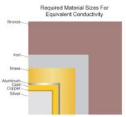
Handy-dandy visual from BlueSea https://www.bluesea.com/resources/108/Electrical_Conductivity_of_Materials#
1709588774724.png
As they note: -
Perhaps the most interesting fact revealed by this chart is how low most copper alloy materials rank in relative conductivity. One might easily assume that alloys such as the brasses and bronzes, because they are mainly copper, are nearly as conductive as copper. This is not the case. The small percentages of tin, aluminum, nickel, zinc and phosphorus that make up these alloys degrade the electrical performance of the resulting alloy to a far greater percentage than their compositional percentage in the alloy.
 
Something to keep in mind is that conductivity is not the same as current rating.

As you increase the brass bus bar size, the larger size will take more heat for any given temperature. At some point, the brass bar reaches the same operational temperature even though it is still greater resistance than the copper.

Assuming heat capability grows linearly with surface area (square root of cross sectional area), and brass being 28% the conductivity of copper, then a brass rod 1.375 times the diameter of a copper rod will get as warm. The brass rod will be 53% as conductive as copper, and generate 89% more heat, but end up the same temperature, therefore will have the same current ratings.

If all you care about is the rating and not the losses, then the brass doesn't have to be that much bigger, 38% more diameter, 89% more area.

Mike C.
 
Last edited:
Most have a decent stud to stack the terminals. A middle stud stack B1, Inverter, B2 on top. No washers etc between the lugs. Use the other studs for small loads.
 
Back
Top