diy solar

diy solar

What determines your battery-inverter bus bar size?

jfharper

New Member
Joined
Jul 23, 2021
Messages
174
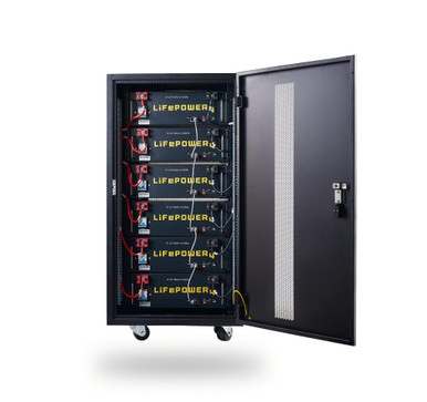
From Wills old 48v off grid 240v split phase blueprint, he listed current connected 300 amp bus bars when going from 2x6500ex to a six rack of lifepower4.

So each 6500ex says 153amps per inverter for battery connection. But the solar setting charges at 60amps and the ac output is set at 60amps. So is the 153amps all this combined plus a bit more for the conversion loss?

Also, if I wanted to connect 4x6500ex to the same rack mentioned above, I would need a 300amp for each 2 inverters, (red and black) and a 600amp to the rack from each of those 300amp bars? Do I have that correct? Also, 2/0 is good for all except from the 600amp to rack which needs 4/0…which I’m running based off Wills blueprint…correct?

If I added another six pack rack in the future, I could connect it to the 600amp bus bar mentioned above via 4/0….correct?

Or better yet, one 600amp bus bar, all inverters connect to and racks can too…?
 
Last edited:
I've been reading a lot about bus bars and sizing and current handling for a cross sectional area. Then reading on fusing and other things. I haven't built these yet, just been doing reading so take what I write below with a grain of salt.

So, the net result bus bars should be sized for the absolute max current that can be passing through it at an given time + 20%.

You can have 153 amps per inverter draw or you can have 60 amps per inverter charge. Can the inverter charge and draw at the same time...no. So figure for the draw only of 306 amps. Assuming the PV is hooked to the inverter verse being a separate charge controller you only need to worry about the 306 amps - Now add the 20% and you get 367 amps. Are you ever going to sustain the 153 amp draw - I assume at times.

Now, I don't see a link for the bus bars Will used in his video but the Positive one looks just like this one:
These are nickle plated brass and assuming they have the right cross-sectional area or are similar to some I have in hand they actually can handle 308amps.

The negative bus bar has a different style cover that looks like others I have seen rated at 300amps. I have some made by LiTime that are just relabels of this style, but there are also a lot on amazon that look like this that I wouldn't trust to handle half that current. For the sake of this lets assume they also carry 308amps.

Are you going to run continuously at 306 amps flat out? Probably not. Can you get away with 300amp bars and never look back, 99% chance they would get warm or hot from constant max current.

Are you doing grid tie? If so you probably want to actually go to 600amp bars so the inspector doesn't flag them.

Is this what you are looking at?

They have bus bars included inside the rack to hook the batteries together so you only have to tie in to the system. In his video he has the cables tied to the bus bar on the wall to a Class T fuse then on to each inverter.

I don't know what fusing he used inside the case to protect the wiring to the bus bars but I would personally add a class T there as well.

Wire sizes - 4/0 between the bus bar and the battery rack. 2/0 between the bus bar to the class T fuse to the inverter.

Class T fuses + holders - The blue sea systems units with the latching cover is why easier to open than the snap down covers. And there is a difference in size starting at 300amps. So make sure to get the right size holder/fuse
 
Last edited:
I've been reading a lot about bus bars and sizing and current handling for a cross sectional area. Then reading on fusing and other things. I haven't built these yet, just been doing reading so take what I write below with a grain of salt.

So, the net result bus bars should be sized for the absolute max current that can be passing through it at an given time + 20%.

You can have 153 amps per inverter draw or you can have 60 amps per inverter charge. Can the inverter charge and draw at the same time...no. So figure for the draw only of 306 amps. Assuming the PV is hooked to the inverter verse being a separate charge controller you only need to worry about the 306 amps - Now add the 20% and you get 367 amps. Are you ever going to sustain the 153 amp draw - I assume at times. So the safety factor is probably important to avoid heating.

Now, I don't see a link for the bus bars Will used in his video but the Positive one looks just like this one:
These are nickle plated bras and assuming they have the right cross-sectional area or are similar to some I have in hand they actually can handle 308amps.

The negative bus bar has a different style cover that looks like others I have seen rated at 300amps. I have some made by LiTime that are just relabels of this style, but there are also a lot on amazon that look like this that I wouldn't trust to handle half that current. For the sake of this lets assume they also carry 308amps.

Are you going to run continuously at 306 amps flat out? Probably not. Can you get away with 300amp bars and never look back, 99% chance they would get warm or hot from constant max current.

Are you doing grid tie? If so you probably want to actually go to 600amp bars so the inspector doesn't flag them.

Is this what you are looking at?

They have bus bars included inside the rack to hook the batteries together so you only have to tie in to the system. In his video he has the cables tied to the bus bar on the wall to a Class T fuse then on to each inverter.

I don't know what fusing he used inside the case to protect the wiring to the bus bars but I would personally add a class T there as well.

Wire sizes - 4/0 between the bus bar and the battery rack. 2/0 between the bus bar to the class T fuse to the inverter.

Class T fuses + holders - The blue sea systems units with the latching cover is why easier to open than the snap down covers. And there is a difference in size starting at 300amps. So make sure to get the right size holder/fuse
Finally got the chance to read this, thanks for your help. Yes, those are the bus bars I have,and yes that is the rack I have. 4/0 going from the rack to the bars, 2/0 from bars to Nader breaker then to inverters. Will mentioned using beakers or fuses, some do both, I haven’t decided if I want to add the fuse.

Thinking I could just mill a mondo piece of metal conductor and mount that to the concrete wall…my wife didn’t like that idea.

I don’t get the Nader breaker thing. SS says they are 200amp, but Nader says 100amp, then SS says they use two in configuration for 200 amp…they show one but advertise 200amp…that I don’t get. Anyway, I’m running one per inverter so I assume if the inverter exceeded 100 amp the breaker should trip.

I’d like to figure what would determine my max draw…I’ll have to research and calculate that.

I’d like to see if I could get away with something like these. https://www.currentconnected.com/product/victron-600a-4-stud-8-stud-busbar/
 
Last edited:
Thinking I could just mill a mondo piece of metal conductor and mount that to the concrete wall…my wife didn’t like that idea.
The best bus bar you can get is a '69 mustang. Just put that in the garage and bolt all your wires to it. Might need 2, though (positive and negative)

Alternatively, get a blue sea bus bar rated for your expected current. Or just default to the 600a
 
Anyone had success stacking inverter connectors to a single stud on the bus bar?
 
I’ve been thinking about trying these vs the nader
IMG_2295.jpeg
 
Anyone had success stacking inverter connectors to a single stud on the bus bar?
It has been noted on the forum by a few that you can 'double stack' the ring terminals, if you need to. I prefer to use a long enough bus, that each inverter has it's own stud. If you ever need to do work on the system, you can remove a single cable without affecting other units if they are each on separate studs.
 
Get a busbar rated for your max load. But, if you stagger the connections, the max amps through any one point will be a fraction of that.

Inverter 1 - battery - inverter 2

300 amps from the battery splits to 150 amps to each inverter
 
Get a busbar rated for your max load. But, if you stagger the connections, the max amps through any one point will be a fraction of that.

Inverter 1 - battery - inverter 2

300 amps from the battery splits to 150 amps to each inverter
For me would I do
Inv1-inv2-battery-inv3-inv4
 
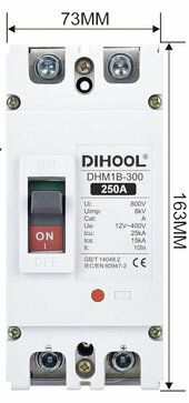
I wouldn't do one with that high of an amp rating. It would work fine as a disconnect, but the whole point of the breaker is to protect the wire from an amperage standpoint. If you are using wire that can carry 15-25 THOUSAND amps, I'd like to see it ;)
I have 200a BMS in each battery, hence the 250a breaker
ICS and ICU refer to its ability to be put back into service in reacting to those amperage thresholds no?
Note: each battery is also fused prior to breaker
 
Last edited:
I have 200a BMS in each battery, hence the 250a breaker
ICS and ICU refer to its ability to be put back into service in reacting to those voltage thresholds no?
Note: each battery is also fused prior to breaker
Yeah I see now. I really shouldn’t comment when I’m too blind to see the big 250A rating above the other specs - lol 😂
 
I have. 4/0 going from the rack to the bars, 2/0 from bars to Nader breaker then to inverters.
What is your logic going from 4/0 to 2/0? Is the length of 2/0 very short? It's seemed from one post that this was a situation of one battery and two inverters? If so, that would be an explanation.
 
Back
Top