diy solar

diy solar

Critique my semi-portable planned setup

thundernanananah

New Member
Joined
Dec 14, 2019
Messages
6
I have no experience and this build doesn't have a specific goal. Mostly to gain experience, it looks like fun. I may work up to an off grid solar shed project later.

It's only real practical use will be to go camping. I've already bought the most expensive components (battery, inverter, MPPT) as well as the fuse block, negative busbar and circuit breaker. I'd rather not replace anything unless necessary. Mostly made choices based on specials I got - some parts I've had sitting unused for 6+ months.

I also already have a 12/24V DC + 120/240V AC camping fridge.

The system is massively over-specced. The planned DC appliance draw is never likely to go above 300W. The inverter is there just in case I need AC, no dedicated purposes. I might use my mini Instant Pot on it which doesn't go above 330W while pressure cooking.

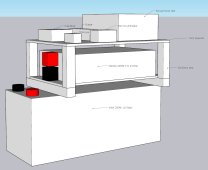
I've tried to make it semi portable but it will generally require two people to safely move. It'll be about 30cm wide, 50cm tall and 55cm long at it's maximums. And once put together I'd say about 34-35kg. The battery comes with handles that I intend to use for carrying/moving.
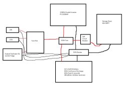
offgridsemiportable-paint.jpg
offgridsemiportable-3d.jpg

My concerns:

The inverter won't vent well enough. I'm not too worried about the inverter venting 'cause it'll almost always be off and be drawing waaaaay below it's max draw for the brief periods it's on. While my lifelike 3D rendering may fool you into thinking there's no space below the inverter, there is a ~1cm gap.

Protecting the battery and inverter terminals. Having them this close to each other seems like a recipe for a potential short and bad consequences. How can I protect them?

The shunt/monitor seems a waste for such a basic messing about build. I put the MPPT on top so I can see the screen easily and that has a battery voltage monitor. But I'm guessing I should get one.

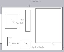
Not enough space around the busbar/fuse/fusebox/breaker for cabling. Looks pretty cramped. There won't be a tonne of cables but some will be chonky. Since I have no experience it's hard for me to judge. Here's a top down of it, the board is 430x300mm and the area for all that is about half that. Everything measured and to scale:
offgridsemiportable-topdown.jpg

Thanks to anyone who takes a look.
 
I'm left wondering if no news is good news or if it's just so bad that no-one thinks it's salvageable or worth commenting on.
 
Hi,

I am far from an expert, but how did you come up with a 150A fuse for your inverter?

The sizing goes 2,200/0.9 (assume90% efficency)= 2444 W; Divide by battery voltage; = 203A ; X 1.25 Safety Factor = 254A I guess you say your max load is 330W? Then why such a large inverter? What is the size of your AC?

Why is your solar controller wired into the fuse?

I would recommend a positive bus bar.

I bought these to protect my battery posts. https://www.amazon.com/gp/product/B08RJ2SHKY/ref=ppx_yo_dt_b_search_asin_title?ie=UTF8&psc=1

My inverter came with covers for the terminals, but there is still some exposed parts. I wrapped them with a bit of electrical tape.

Are you going to bend the thicker cables inthe tight configuration? I have a 2000W inverter and used 2/0 cables. Also, the wiring might be a challege for all the other componets so close together...just something to think about.

I would put in a cut off switch in front of the inverter and fuse box so you can turn the power of for repair, troubleshooting, etc.
 
Any "why" question is largely going to be answered by "I have no experience and this build doesn't have a specific goal". If you want me to defend my inexperience or lack of goal I'm not sure where to start. When I say I have no experience I'm not using hyperbole: none. This isn't some kind of "hey, back off man, I'm just a beginner" I'm just letting you know the situation - I will take instruction because I literally do not really know what I'm doing. If I sound defensive I just want to be clear: I'm not. If someone says "no that's all wrong do this instead" and it doesn't look like you're trying to get me to attach jumpers to my balls I'll do it.

As mentioned in the OP the reason for the components is they were gathered over a period of months based on available specials. With a mind to this stuff being pulled apart for other things later. Good deal at the time for a non-specific build, now this is what I have to work with. Specifically these are the things I have already:
VoltX 200Ah Basic
Giandel 2200W/4400W
Renogy Rover 40A
50A circuit breaker (manual version)
150A BlueSea busbar
10 fuse fusebox (generic)

These are already bought. I can replace them if needs be but it's what I have.

The max DC load I can figure is 300W, the max AC is 330W. Combined 630W. Plus inefficiencies let's say 750W combined to be on the safe side.

The 150A fuse is a kind of positive busbar? But with a fuse function. That's the intention at least. Something like this, I think it's linked in a Will/mobile-solarpower.com build. My understanding is you can connect up to three things to a single point? The plan was the battery on one side, everything else on the other. So no matter what pushes/pulls over 150A the fuse goes. The idea being if anything goes **WAY** over the intended usage of < 750W the fuse blows.

Also the battery BMS should cut things off if the draw is over 100A for more than 5 seconds. I guess you can't rely on that though, especially on a cheapo brand like this battery is.

Terminal protects handy, thankyou. The terminals on the Giandel inverter are protected from each other, pointing in opposite directions and having plastic in between but when I put those terminals near the battery terminals it'll become more iffy. Electrical tape as well as the silicon protects seems a good idea, just in case.

Any suggestions on what cut off switches to get?
 
Geez..sorry ...my why question was just to understand your approach. Never said anything was wrong. Just offered suggestions what I've learned over the last few months. Maybe you had reasons...like 1. I got it off another set up, 2. Someone else suggested it to me or I just guessed. Any of those are ok... I get it. I just installed my first system. Had to make many changes based on this and other sites. Returned many parts. Lot of good resources here if you have not seen them. https://diysolarforum.com/resources/categories/beginners-resources.10/

Any 12V cut off switches rated to the amps of your system. These can be used https://www.amazon.com/dp/B00445KFZ2?psc=1&ref=ppx_yo2ov_dt_b_product_details https://www.amazon.com/gp/product/B07MQ54KKH/ref=ppx_yo_dt_b_search_asin_title?ie=UTF8&psc=1
 
In the link below is my build for when I go tent camping. The one item from your plan that jumps out at me is that there is no circuit breaker between the PV and the solar charge controller. That breaker should be a dual pole breaker. In case you need to disconnect the system while the sun is on the panels, you need to break the circuit. MC4 connectors (the most common connector on solar panels) should not be disconnected under load. When shutting down the system, the rule is to disconnect the PV first, then disconnect the battery. When starting up the system, battery first, then PV.

Until you've been there, it's hard to design a system in CAD that takes into account wires. The more room you can leave between components and how you arrange the components, the easier it will be to wire.

 
I also have limited experience, and am building a 'similar' portable battery thing atm.

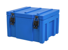
I don't see it mentioned, but what stands out to me is not knowing how/where this is going to be used/moved around. you mentioned moving around with handles from the battery, does this mean that other shit is just strapped to the top? why don't you put this in a large box?

I am planning to use mine in a small shed setup, but also taken with me in a camper trailer occasionally. So I am using a 400x600x550mm cargo container ($120usd new)

Also, I know you have bought a lot of the components, but would you consider an all-in-one type inverter? I don't know your current inverter, it looks pretty good, an all-in-one might not be 'the best' but if your loads are generally pretty low, and it is easier to setup / transport then it s worth considering.

I went with an MPPsolar 'hybrid' inverter is 24v 4000w AC inverter / solar charger, and AC charger (which you haven't listed, do you plan on only using with solar?) in a unit that isn't too much larger than yours 300x430x115 vs 230x404x94 (14.8L vs 8.7L). you can definitely find a 12v 2400w model much smaller.

As HRTKD above said above, DO NOT underestimate the room needed for wires. I similarly tried to design it all in sketchup, but once everything starts to get placed loosely you realise that it's going to get really messy.

Good luck


2023-02-18 08 34 59.png
 
@Chaucer when you asked why I assumed you wanted more than what I explained in the OP, which is that I bought parts as specials came along over several months. As said - there is no more.

@HRTKD there is a circuit breaker there, the manual one here. Is that sufficient?

@Samtrois if I do another build I probably will go with an all in one. I do want to try using these first, I can learn more that way.

My plan to keep the stuff on top of the battery is definitely iffy. Wood frame on top of battery. Frame has a couple of metal strips made from strapping nailed/screwed at the bottom. Two or three ratchet straps holding those braces around the battery.

With the odds there'll be too much wiring to fit on the top plyboard that might completely scrap the plan. Hmm.
 
With the odds there'll be too much wiring to fit on the top plyboard that might completely scrap the plan. Hmm.
Just seems a bit iffy to me if you start taking it camping, and it's just a jenga tower of 'exposed' cables.
You should be able to squeeze that into a box of some type. Check your big chain hardware stores, a toolbox on wheels is a popular option.

Being in the box gives you the obvious 'safety' of not having so much exposure. but also so many more surfaces to mount things too.

Could you sell that inverter + charger?
 
Last edited:
@HRTKD there is a circuit breaker there, the manual one here. Is that sufficient?

In your first diagram, the solar panels are not shown and there is no circuit breaker upstream of the solar charge controller. The breaker you linked to is fine for downstream of the solar charge controller, and 50 amp is the right size. A breaker that covers only the positive cable is not recommended for between the solar panels and the solar charge controller. You want a dual pole breaker that covers both positive and negative wires.
 
@HRTKD Ah, thankyou, will add one.

@Samtrois yeah, the wiring might completely screw this one. Not enough space and a bit of a hazard. I think I'll give it a go as is, with low expectations. All the things on top have covers for the terminals so I'm not too worried about that but the wires/cables themselves, yeah. The cost of the wood is nothing so I may as well get a feel for the space. Mount everything just to see if it down all come together and be carry-able without any of the wiring. If it looks workable then try to add the wiring and see just how much of a mess that is. That'll be the expensive part 'cause it'll be cut to size and probably not reusable on the inevitable reconfiguration.

Any opinions on that positive fuse? Should I be changing it to a busbar with a fuse on the battery side (and/or on other things)?
 
Back
Top