


Hi All,
First post here after a few days of using these forums to try to discover why my Daly BMS would not activate. Before I start I should state that I do hobby electrical engineering and have enough experience to say with certainty that I did not damage the BMS. All wiring was correct and verified before connecting the BMS as per the instructions (this is proven later too as the exact failure was discovered).
So why did I risk a tear down? There was shipping damage to my battery cells from China to Aus and as it took so long to get them replaced, by the time I could test the BMS it was out of warranty.
Things I tried were:
* power the bluetooth module directly with 3.3V
* Connect to the UART directly with a TTL adaptor, which when I did, caused the adaptor to fail to be recognised by the PC. The 3.3V output of the adaptor was being pulled down to around 2V indicating the adaptor I was using could not supply enough current.
So I reconnected the BMS to the battery pack and noted that the 3.3V pin on the UART connector was pulsing on for a few us at a time on a DSO, this is a good indication of a LDO regulator going into overload protection (possible shorted rail). It was time to dig deeper.
After watching another person attempt this on Youtube and seeing him tear parts off the PCB I decided to use some hot air to soften the potting compound and was able to remove it without any damage. Took about an hour to fully depot the device.
Interesting things of note on inspection:
* There is a LED on the PCB (kind of pointless when it's potted)
* The MCU is a GD32E230C8T6 (STM32 like device, similar to the F1 series, very nearly pin compatible but register base addresses are different)
* There are four pads on the PCB near the MCUthat look like they might be a debugging UART is the STLink Serial Wire Debug (see post #6 for pinout)
* There are footprints for several additional connectors on the opposite side marked "KEY", "DIO", and "SW"
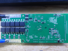
* It seems the number of cells the BMS is designed for can be adjusted by moving the zero ohm resistor (or adding more) on the back near the sense connector at the edge of the PCB. S16 seems to be the highest number before additional parts are needed on the PCB, but it could be possible to turn this into anything less simply by moving/adding shorts there to reconfigure it.
General things of note:
* No physical damage
* No burn/brown marks or the distinct burning electronics smell.
* No shorted or open mosfets
So the first hint I had was the 3.3V pin going into what looked like a fault, as such checking for a short on the 3.3V rail was the first thing to do. Between that pin and ground there was no short, however there is a 3.3V SOT32 LDO on the PCB that is to provide power the GD32E230. Checking this regulator showed a short between it's output and ground and removing this regulator did not remove the short.
So I removed the MCU with hot air (more potting compound oozed out from under the chip when I did this) and again tested for a short... and it was gone. Now when connecting the USB UART TTL adaptor, it works as expected. Checking the VSS and VDD pins on the MCU IC itself reads a dead short.
So, the MCU had failed from factory. Thankfully this device is VERY similar to the STM32 family which I am intimately familiar with (I am the original author of stm32flash) and I found someone has posted a firmware upgrade file for their BMS which is just in standard intel hex format. As such I have ordered a replacement MCU and will attempt to repair this device when it arrives.
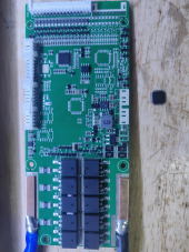
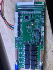
Attached images of the device after removing the MCU and noting the 3.3V rail is no longer shorting, resulting in the LED lighting up when the UART is connected.
First post here after a few days of using these forums to try to discover why my Daly BMS would not activate. Before I start I should state that I do hobby electrical engineering and have enough experience to say with certainty that I did not damage the BMS. All wiring was correct and verified before connecting the BMS as per the instructions (this is proven later too as the exact failure was discovered).
So why did I risk a tear down? There was shipping damage to my battery cells from China to Aus and as it took so long to get them replaced, by the time I could test the BMS it was out of warranty.
Things I tried were:
* power the bluetooth module directly with 3.3V
* Connect to the UART directly with a TTL adaptor, which when I did, caused the adaptor to fail to be recognised by the PC. The 3.3V output of the adaptor was being pulled down to around 2V indicating the adaptor I was using could not supply enough current.
So I reconnected the BMS to the battery pack and noted that the 3.3V pin on the UART connector was pulsing on for a few us at a time on a DSO, this is a good indication of a LDO regulator going into overload protection (possible shorted rail). It was time to dig deeper.
After watching another person attempt this on Youtube and seeing him tear parts off the PCB I decided to use some hot air to soften the potting compound and was able to remove it without any damage. Took about an hour to fully depot the device.
Interesting things of note on inspection:
* There is a LED on the PCB (kind of pointless when it's potted)
* The MCU is a GD32E230C8T6 (STM32 like device, similar to the F1 series, very nearly pin compatible but register base addresses are different)
* There are four pads on the PCB near the MCU
* There are footprints for several additional connectors on the opposite side marked "KEY", "DIO", and "SW"
* It seems the number of cells the BMS is designed for can be adjusted by moving the zero ohm resistor (or adding more) on the back near the sense connector at the edge of the PCB. S16 seems to be the highest number before additional parts are needed on the PCB, but it could be possible to turn this into anything less simply by moving/adding shorts there to reconfigure it.
General things of note:
* No physical damage
* No burn/brown marks or the distinct burning electronics smell.
* No shorted or open mosfets
So the first hint I had was the 3.3V pin going into what looked like a fault, as such checking for a short on the 3.3V rail was the first thing to do. Between that pin and ground there was no short, however there is a 3.3V SOT32 LDO on the PCB that is to provide power the GD32E230. Checking this regulator showed a short between it's output and ground and removing this regulator did not remove the short.
So I removed the MCU with hot air (more potting compound oozed out from under the chip when I did this) and again tested for a short... and it was gone. Now when connecting the USB UART TTL adaptor, it works as expected. Checking the VSS and VDD pins on the MCU IC itself reads a dead short.
So, the MCU had failed from factory. Thankfully this device is VERY similar to the STM32 family which I am intimately familiar with (I am the original author of stm32flash) and I found someone has posted a firmware upgrade file for their BMS which is just in standard intel hex format. As such I have ordered a replacement MCU and will attempt to repair this device when it arrives.
Attached images of the device after removing the MCU and noting the 3.3V rail is no longer shorting, resulting in the LED lighting up when the UART is connected.
Attachments
Last edited:
")
