diy solar

diy solar

Daly BMS settings for protection parameters

JPTOSHI and Nathaniel, unfortunately this is all I have and got these from Daly. A lot you have to copy and paste to address bar. Wish I had more for you. Nathaniel one of these links above should have the parameters you are looking for. Daly usually preprograms the newer "smart" bms's which is what I have. Sorry I'm not more help.
 
Hello,
can anybody help me ?
I search for the correct Parameters for the following Pack:

8 x 120Ah LiFePo4 3,2V (2 x parallel and then 4 in a row) = 12V 240Ah
1 x DALY SMART BMS 250A with BT and USB

the German translation in the Android App is .... great (NOT)

can anyone help me to find the correct settings ?

the Battery will be used in a Motorhome.

greets
Martin
 
Here are the settings I use for my Daly Smart BMS 150A 8S 24V
cell volt high protect - 3.68V
cell volt low protect - 2.50V
sum volt high protect - 28.5V
sum volt low protect - 22.5V
diff volt protect - 0.10V
chg overcurrent protect - 80A
dischg overcurrent protect 80A
battery type - LFP/LifePO4
rated capacity - 280.0AH
cell reference volt - 3.60V
sleep waiting time - 65535S
balanced open start volt - 3.00V
balanced open diff volt - 0.05V
chg high temp protect - 40C
chg low temp protect - 5C
disChg high temp protect - 38C
disChg low temp protect - 10C
diff Temp protect - 15C
MOS temp protect - 40C

I hope it helps.
 
Last edited:
Here are the settings I use for my Daly Smart BMS 150A 8S 24V
cell volt low power - 3.68V
sum volt high protect - 28.5V
sum volt low protect - 22.5V
diff volt protect - 0.10V
chg overcurrent protect - 80A
dischg overcurrent protect 80A
battery type - LFP/LifePO4
rated capacity - 280.0AH
cell reference volt - 3.60V
sleep waiting time - 65535S
balanced open start volt - 3.00V
balanced open diff volt - 0.05V
chg high temp protect - 40C
chg low temp protect - 5C
disChg high temp protect - 38C
disChg low temp protect - 10C
diff Temp protect - 15C
MOS temp protect - 40C

I hope it helps.

Hi,
you use it as a 24V system --- i use it at 12V

are there any other settings ?

for example:
sum volt high protect - 28.5V ?
sum volt low protect - 22.5V ?
 
Hi,
you use it as a 24V system --- i use it at 12V

are there any other settings ?

for example:
sum volt high protect - 28.5V ?
sum volt low protect - 22.5V ?
I'm not sure for 12VDC. The values I used for 24V, I kind of figured out by reading thru some of the posts.
Maybe you can use 14.25V for high protect and 11.25 for low protect.
Otherwise, someone more knowledgeable might chime in and provide proper values.
 
I use 14.4V for mine. 3.6v * 4 cells. I also have 8 total cells but I like the 8 cell battery vs the two 4 cell batteries in parallel. I just personally have an easier time with setup.
1614535139555.png
Some information I found on another thread. Hope this helps
 

Daly 18650 smart LiFePO4 4S BMS 12V 150A 200A 250A Bluetooth 485 to USB device CAN NTC UART togther Lion LiFePO4 LTO Batteries​


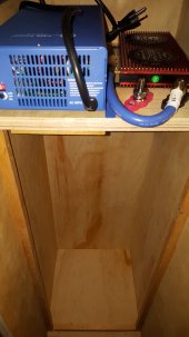
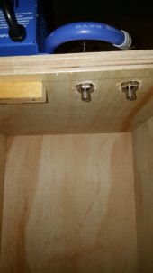
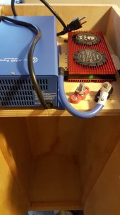
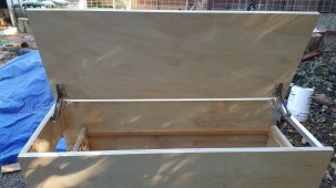
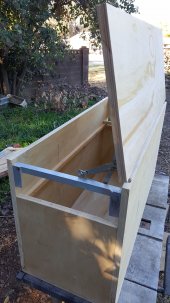
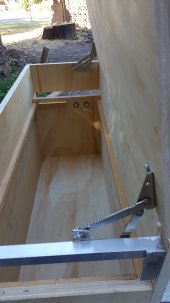
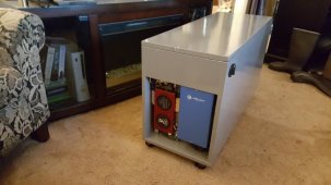
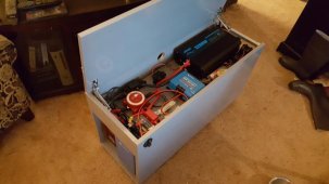
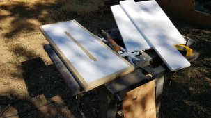
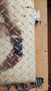
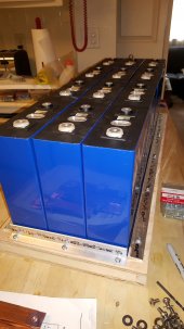
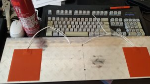
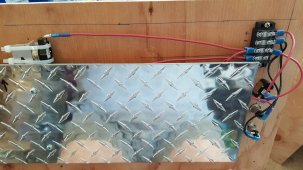
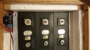
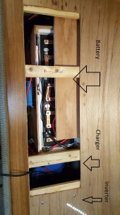
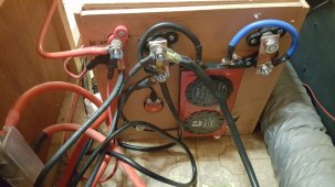
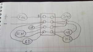
Single BMS - batteries are connected in series and parallel using 1/2" copper pipe flattened & drilled. BMS sensors are attached to center post on each group of 3. Not sure it matters now - BT quit working for me just overnight. Installed and working fine yesterday. Haven't got the UART working yet, having difficulty on both my computers with com ports. While I had it working, I noted that set #2 was reading 3.6 while the other three were reading 3.3 (in round numbers, they were close to what I've listed here). I did top balance the first two sets I got (at 3.8v), for like two-three weeks - and the amperage never seemed to change or changed so slowly they could have been on there forever... the third set I put on to top balance with the others for like four days, same pattern, so I went ahead with the install at that point. Am I right in thinking these will all balance out by virtue of being linked together like this, eventually? I was surprised that even after all that time in balancing that when I first got the BT up and running it showed the bank at only 33% capacity, and charged at 80 amps for about an hour and a half before reaching "float" mode.

ETA: I've tried unplugging the BT module, restarting the phone app, reinstalling the phone app - worked perfectly yesterday, zippo today. I had ordered a spare BT module when I thought the first one got lost in the shipping channel (it eventually did arrive) - Got it out just now to see if swapping would fix anything - Now I am seeing that the connector to the BMS is different (second one has a plug about 2x as wide as the first) so no joy there either. Thanks, Daly...

ETA2: I was able to swap cords on the modules. Module #2 is now online and apparently working fine... at least for now.

ETA3: Now the second one isn't connecting!! Arrrgh! Swapped back and forth a few times... now neither module is working. I may be about to resort to foul language here.

ETA4: Just checked and the app is now finding the BT module again. Looks like it's just a random thing, works when it feels like it. Or, it took my threat of speaking harshly to it seriously.

View attachment 31642View attachment 31645View attachment 31647
Looks like a nice build. Think of the same. Would you be willing to share a bit more of the details of your battery build? Thank you in advance.
 

Daly 18650 smart LiFePO4 4S BMS 12V 150A 200A 250A Bluetooth 485 to USB device CAN NTC UART togther Lion LiFePO4 LTO Batteries​

. . . I did top balance the first two sets I got (at 3.8v), for like two-three weeks - and the amperage never seemed to change or changed so slowly they could have been on there forever... the third set I put on to top balance with the others for like four days, same pattern, so I went ahead with the install at that point. Am I right in thinking these will all balance out by virtue of being linked together like this, eventually? I was surprised that even after all that time in balancing that when I first got the BT up and running it showed the bank at only 33% capacity, and charged at 80 amps for about an hour and a half before reaching "float" mode . . .
I assume you're using LifePo4 chemistry, right? Is it safe to top-balance at 3.8v? Sounds a bit high. I always thought the ceiling for top-balancing was 3.60v - 3.65v.

As for the Daly SOC meter, I've found it must hit the low voltage (discharge) and high voltage (charge) cut-offs one or two times to establish a solid 0% and 100% SOC baseline. Once that's established the SOC meter becomes much more accurate. Also, the default values Daly uses for the System->Voltage of Capacity xx% entries (via Sinowealth) seem to be a bit too high. A number of folks have lowered the 10% to 100% values and improved the SOC meter's accuracy.
 
Here are the settings I use for my Daly Smart BMS 150A 8S 24V
cell volt high protect - 3.68V
cell volt low protect - 2.50V
sum volt high protect - 28.5V
sum volt low protect - 22.5V
diff volt protect - 0.10V
chg overcurrent protect - 80A
dischg overcurrent protect 80A
battery type - LFP/LifePO4
rated capacity - 280.0AH
cell reference volt - 3.60V
sleep waiting time - 65535S
balanced open start volt - 3.00V
balanced open diff volt - 0.05V
chg high temp protect - 40C
chg low temp protect - 5C
disChg high temp protect - 38C
disChg low temp protect - 10C
diff Temp protect - 15C
MOS temp protect - 40C

I hope it helps.
Your cell reference voltage is 3.6v.
Is that preferred for 24v setups ?
I have 3.2v for cell reference for my 12v 2p4s 640ah setup but now wondering if I should change the cell reference volt.
 
Your cell reference voltage is 3.6v.
Is that preferred for 24v setups ?
I have 3.2v for cell reference for my 12v 2p4s 640ah setup but now wondering if I should change the cell reference volt.
Here are the settings I use for my Daly Smart BMS 150A 8S 24V
cell volt high protect - 3.68V
cell volt low protect - 2.50V
sum volt high protect - 28.5V
sum volt low protect - 22.5V
diff volt protect - 0.10V

My diff volt protect is stuck on 0. When my battery has a big load I think this is causing my battery to turn off. When I put in .1 and the password the value shows up again in the input field but doesn't change on the card. Is there something im missing?
 
Looks like a nice build. Think of the same. Would you be willing to share a bit more of the details of your battery build? Thank you in advance.
I'll supply some photos. Sorry I'm just now seeing this.
 

Attachments

  • Power Box 1.jpg
    Power Box 1.jpg
    93.2 KB · Views: 46
  • Power Box 2.jpg
    Power Box 2.jpg
    61.4 KB · Views: 45
  • Power Box 3.4.jpg
    Power Box 3.4.jpg
    119.9 KB · Views: 43
  • Power Box 3.5.jpg
    Power Box 3.5.jpg
    143.4 KB · Views: 41
  • Power Box 3.jpg
    Power Box 3.jpg
    93.3 KB · Views: 44
  • Power Box 4.jpg
    Power Box 4.jpg
    268 KB · Views: 37
  • PowerBox 5.jpg
    PowerBox 5.jpg
    154.5 KB · Views: 35
  • PowerBox 6.jpg
    PowerBox 6.jpg
    90.5 KB · Views: 38
Looks like a nice build. Think of the same. Would you be willing to share a bit more of the details of your battery build? Thank you in advance.
Here's the finished product. The polarized plug on the side is for the DC in from the 630w solar array. It can be unplugged and wheeled away. If you have questions, feel free to ask.

The lower compartment contains twelve 3.2v 280 ah LiFePO4 cells, connected in three rows of 4 for a nominal 12v battery system. On one end of the cabinet the BMS (Daly 12v 250amp 4S) and the charger are mounted vertically, for passive heat dissipation. On the cover over the lower compartment (which is removable to access the cells) is mounted a master-switch, fuses, Victron 100/50 MPPT charge controller, and 2200w pure sine wave inverter. There is also a 7-outlet USB charger for phones, tablets and other devices. Cabinet construction is 3/4" plywood, nailed and glued with carpentry glue. Cells are internally braced with aluminum "L" bracket on the floor of the compartment, and at the top with 3/4" square tube - very snug fit.
 

Attachments

  • PowerBox - Finished 1.jpg
    PowerBox - Finished 1.jpg
    42 KB · Views: 59
  • PowerBox - Finished 2.jpg
    PowerBox - Finished 2.jpg
    43.9 KB · Views: 56
  • PowerBox - Finished 3.jpg
    PowerBox - Finished 3.jpg
    40.6 KB · Views: 66
Last edited:
The original was for use as a general purpose home power backup. I tested it around groundhog day, and with typical weather I was able to run our refrigerator for 10 consecutive days while attached to 630 watt's worth of solar panels. The cells were still reaching 99-100% by sunset each day.

I've just completed a simpler version of this to replace the dead lead-acid batteries on my travel trailer. Here are some pics of that effort. It's a smaller BMS because on the trailer I'm more concerned about how long the power lasts rather than how fast I can burn through the stored juice. I did insulate this one and made sure that the warming circuit worked before getting it all together. Button thermostat triggers at 35 degrees F, which turns on the silicone warming mats, shutting off at 45 F. The floor is 3/4" styrofoam sandwiched between two 5/16" plywood sheets, with 3/4" pine for the frame & center support. The diamond plate never touches the cells, it's about a half inch away so there's room for air circulation. This battery array is fed from three 140w 12v panels on the trailer roof.
 

Attachments

  • Corner Support and Tube.jpg
    Corner Support and Tube.jpg
    568.5 KB · Views: 19
  • Corner Support and Tube 3.jpg
    Corner Support and Tube 3.jpg
    459.1 KB · Views: 19
  • 01 - Battery Box Floor.jpg
    01 - Battery Box Floor.jpg
    874.3 KB · Views: 20
  • 003 - Controls with Warming Plate.jpg
    003 - Controls with Warming Plate.jpg
    128.1 KB · Views: 21
  • 04 - Base with Cells Positioned 2.jpg
    04 - Base with Cells Positioned 2.jpg
    116.4 KB · Views: 29
  • 006 - Warming Mats.jpg
    006 - Warming Mats.jpg
    298.2 KB · Views: 24
  • 005 - Controls and Thermostat Wired.jpg
    005 - Controls and Thermostat Wired.jpg
    324 KB · Views: 21
Last edited:
Again, shots of the RV battery box. Terminal setup is a bit messy but works and because this is mounted under the bunk, esthetics is not much of a concern. In both battery projects the aluminum square tube is used for bracing the cells firmly together, so there should be no movement at the battery terminal connections. I had an access hatch already cut in the bunk platform to inspect/maintain the lead-acid batteries that this replaces, so that worked out well. There's just enough headroom under there that I can remove the insulated lid on the battery box for inspection, testing and maintenance if needed. I've included a circuit diagram for the battery warming system. I'm using 12v 12w (x4) silicone mats, a toggle switch and a couple of indicator lights so I know what's going on.
 

Attachments

  • Battery Box 1-Cell Fit.jpg
    Battery Box 1-Cell Fit.jpg
    148.7 KB · Views: 18
  • Battery Box Corner Closeup.jpg
    Battery Box Corner Closeup.jpg
    118.1 KB · Views: 18
  • Battery Box 3-Panel.jpg
    Battery Box 3-Panel.jpg
    455.3 KB · Views: 19
  • Battery Box Neg Fit.jpg
    Battery Box Neg Fit.jpg
    217.9 KB · Views: 23
  • 08 - Under Bunk Access.jpg
    08 - Under Bunk Access.jpg
    142.1 KB · Views: 29
  • 07 - Terminals.jpg
    07 - Terminals.jpg
    477.2 KB · Views: 34
  • Warming Circuit Diagram.jpg
    Warming Circuit Diagram.jpg
    28.8 KB · Views: 29
Last edited:
Looks like a nice build. Think of the same. Would you be willing to share a bit more of the details of your battery build? Thank you in advance.
BTW I eventually got some support from Daly and it turns out the BMS BT goes to sleep if the battery isn't getting power, so it's an undocumented "feature" instead of a bug. Since connecting to the solar panels, the BT has been consistently available.

On the first unit (250 amp) in order to get the BMS to boot up, it was necessary to short between the P- and B- terminals for 15 seconds with the charger attached and "on". This caused the charger and battery to "see" each other, and both came on and stayed on. The second unit (150 amp) this procedure did not work. Eventually I discovered a socket on the BMS labeled "lightboard". I fiddled around in that socket with a metal probe until I heard a faint "click", then the BMS came on and stayed on. I've since ordered a lightboard for convenience.
 
I'm getting beat up today by my 16s smart Daly if anyone is able to lend some advice.
Balanced cables are hooked up TMS is working app is working. The way I can best describe my problem is is that the DMS is cutting off charging at 54 volts or so.
It's being charged by a eco-worthy hybrid inverter that is pushing out 56.5 but the bms is only letting 53.5 through. As far as I can tell my settings are okay. It cycles into a charge mode throwing about 40 amps into the battery bank for a couple seconds and then dials it back.
Appreciate any help
 
I know more people on here have fantastic experience but if you have 16 cells using 3.6v you should get 57.6v. If everything using to measure your voltage agrees, I am going to say some setting somewhere is holding you out. For me it was the charge overcurrent protect was set at 0 by default. This means nothing into the bms. Look on your protection parameter screen and set that to 100. You will hopefully be good to go.
 
Here are the settings I use for my Daly Smart BMS 150A 8S 24V
cell volt high protect - 3.68V
cell volt low protect - 2.50V
sum volt high protect - 28.5V
sum volt low protect - 22.5V
diff volt protect - 0.10V
chg overcurrent protect - 80A
dischg overcurrent protect 80A
battery type - LFP/LifePO4
rated capacity - 280.0AH
cell reference volt - 3.60V
sleep waiting time - 65535S
balanced open start volt - 3.00V
balanced open diff volt - 0.05V
chg high temp protect - 40C
chg low temp protect - 5C
disChg high temp protect - 38C
disChg low temp protect - 10C
diff Temp protect - 15C
MOS temp protect - 40C

I hope it helps.
sum volt hight protect what is that for?
 
Back
Top