Supermans_1
New Member
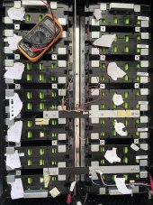
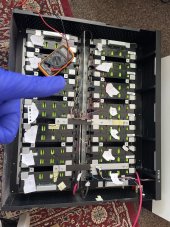
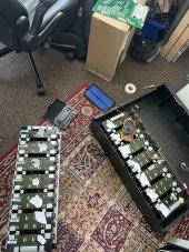
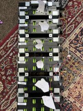
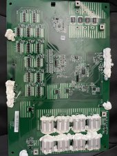
Hi Paul and anyone else interested I've now fitted my third-party dalley BMS 48-volt 14 string 60 amp to my GBL I 5001 I've had a lot to learn with getting the settings right as I opted for the standard plug and play vms without smart function but now happy to say it's working really well i thought i'd share some settings with you see attached photo with attention to voltage battery charge and discharge low and high settings for the charge it seems that this is a range that voltage fluctuates briefly in and out of of the same for discharge voltage fluctuates in and out briefly until discharge and charge functions are satisfied so in other words it's a range see my notes on my settings the charging up has worked really well today day got 3.4 kilowatt hours to 57v and 100% charge
Just to be a bit clearer the voltage battery charge high and low settings I believe this to be a range that the battery starts the stop charging process if that makes sense! And likewise for the voltage battery discharge low and high settings I believe this is a range that the battery starts the stop discharging process
and after discovering the anderson plug problem I have now increased the power to 95% and now no more tripping out !?
View attachment 113172View attachment 113177
I have the shine bus on my laptop but I have non of these settings in the list like vbat hi and lowHi Paul and anyone else interested I've now fitted my third-party dalley BMS 48-volt 14 string 60 amp to my GBL I 5001 I've had a lot to learn with getting the settings right as I opted for the standard plug and play vms without smart function but now happy to say it's working really well i thought i'd share some settings with you see attached photo with attention to voltage battery charge and discharge low and high settings for the charge it seems that this is a range that voltage fluctuates briefly in and out of of the same for discharge voltage fluctuates in and out briefly until discharge and charge functions are satisfied so in other words it's a range see my notes on my settings the charging up has worked really well today day got 3.4 kilowatt hours to 57v and 100% charge
Just to be a bit clearer the voltage battery charge high and low settings I believe this to be a range that the battery starts the stop charging process if that makes sense! And likewise for the voltage battery discharge low and high settings I believe this is a range that the battery starts the stop discharging process
and after discovering the anderson plug problem I have now increased the power to 95% and now no more tripping out !?
View attachment 113172View attachment 113177
Am I doing something wrong
")