Supermans_1
New Member
In lead acid mode with original bms fitted stillNote: everyone's GBLI5001 battery will have different SOC'S.
Upon tinkering with the sp2000 settings in lead-acid mode I couldn't work out why why the sp2000 was still tripping out with error code 118 when charging it turns out that because of lead acid float charging the vbat setting low and high are better off as the same voltage and are better set to the optimum charging value of the battery CAPABILITY - the standard setting is 58 volts for both the settings but because of age and degradation I have changed mine to 56.5 volts (which is 100-percent soc for mine) now the float charging voltage is not active anymore and the sp2000 is no longer tripping out so it's all about the battery capability given its age and degradation ie it will not charge anymore than it can.
And likewise for discharging the vbat low and high settings I think the same principle applies ie my battery discharges to about 49 volts at 50% soc so the setting I have changed to is 49 volts for both vbat low and high to keep the sp-2000 controller from tripping out (Or over discharging)
I'm not sure if the same or similar principles apply for a standard GBLI5001 battery regarding the over charging and over discharging with its original BMS might be worth a few tweaks though if anyone has still got the original setup !
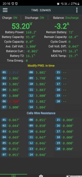
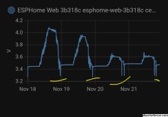
Mine charged to 57.5v 100 percent
Stopped discharging at 47.1v at 40 percent but once stopped discharging voltage went back to 49.2v and now settled back at 49.4v
Charged 3.5kwh today and discharged 3.3kwh
Charged and Discharged much more than is lithium mode
")