Bit of a belated update, but since I started this thread I've managed to finally get a new BMS installed.
To test whether my battery was worthy of spending out on a BMS for, I got a used Sofar ME3000SP from ebay and ran some charge/discharge cycles while monitoring the string voltages manually. It all remained remarkably well balanced considering how low the voltages were when I first opened the battery up! So that was enough to convince me to fork out for the BMS and continue with this battery.
After much deliberation and only after being advised against using a Seplos BMS by a UK importer (due to ongoing QC problems), I went for a JK BMS- the 2A active balancing was too good to pass up and I found this project on here by
@uksa007 -
https://diysolarforum.com/threads/j...support-goodwe-and-pylontech-batteries.48963/, which will allow the JK to communicate with my Sofar by spoofing that it's a Pylontech battery. The more I read about this BMS, the more glad I am that I went with it. I got the 200A version, which I know is way overkill for this battery, but I figured it will be having an easy life in this battery and if this doesn't work out, I can use it for whatever cells I replace it with in the future.
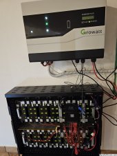
View attachment 152791
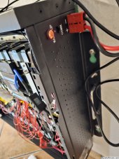
I put the BMS's power button/ status LED in the place of the original LED (just had to drill it out to 12mm). I might well run the BMS comms through the original RJ45 connection on the side to keep everything neat.
I decided to stick a fuse in the positive line as I had one lying around and it seemed a double precaution and neat way to join the wires that used to run through the old BMS. I know there's a factory fuse on the negative line (anyone know its value? I haven't cut open the heatshrink). Interestingly, I've only put in a 30A fuse (nearest I had in stock) and it hasn't blown with the inverter's charge current at 40 A. Maybe due to it being a cheapy from ebay?
So I'm now running tests with functional BMS and inverter running in Default (lead acid) mode ahead of getting the BMS to inverter comms working. All seems to be working pretty well. Will report back once I have some solid capacity figures.
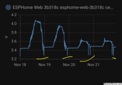
Last night I fully charged it (inverter stopped charging while the BMS was reporting 57.92V, which is a little under the 58.8 that the Boston Swing datasheet says is 100% SoC), then turned off the inverter but left the BMS on and this morning it was balanced down to 0.002 V and sitting perfectly stable!
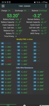
Here's a shot of the JK BMS app's stats page after I've been running everything from the battery for half of the day:
View attachment 152792
The max & min strings are always different, there doesn't seem to be any weaknesses displaying (yet!)
As an aside, I'm interested to know how it calculates the balance wire resistances. I cut the balance wires to suit & if you follow the numbers, S1 is shortest, going up to S7 and S8, then they get shorter again as strings 9-14 get closer to the BMS. How the heck does it figure this out automatically?!


")