diy solar

diy solar

Darfon Gro Watt GBLI 5001 Battery Pack- worth a punt?

Good luck with the project JoshCliffeJones. I am on the edge of buying a new BMS just incase. CattleRustler on this thread: https://diysolarforum.com/threads/darfon-growatt-gbli5001-battery-pack-problem.42129/#post-574308
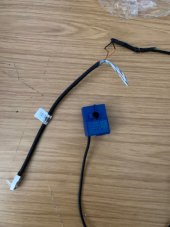
has led me to believe the GBLI5001 battery may also be faulty as a similar situation with his. He has found a little work around. I'm assuming no 3rd party BMS is ever going to communicate with Growatt's protocols, the bluetooth comms sounds good (that will be a BT chip that plugs in UART). The Daly BMS may even give more or allow more info than the current Growatt/Darfon BMS does. Good luck with that and with the CT clamp. I would love to see pics of your handiwork when you get it up an running; I will look forward to the dedicated thread ;)
 
Oh I have another question(s)! I cannot get the software for the SP2000 to run as I would like to change a setting (that 'forced discharge' setting primarily!). I'm trying the get ShinePlusBus.exe to run from the CD, is that the software others are using? I don't have a Growatt WIFI dongle so am using a Serial-to-USB plugged from the RS232 port in to the computer's usb port. The drivers and connection for the serial-usb cable seem ok, it's just the software refuses to load. I'm using an older laptop I've been hoarding which has Win7 64bit on it. Does it need 32bit maybe? Or is there a better chance me using the LAN port instead (and would this connect to a router/switch or directly to a computer and use it's own webpage)? The manual is so not helpful. Thanks.
 
Does anypone know the passcode to get into the AC Charge section on the SP3000? I have the software but it seems a little unreliable and one of my units is charging outside of these times even though I am importing. The other 2 are fine. Re-checked in the software and it's good, and tried power off/on to no avail
 
Oh I have another question(s)! I cannot get the software for the SP2000 to run as I would like to change a setting (that 'forced discharge' setting primarily!). I'm trying the get ShinePlusBus.exe to run from the CD, is that the software others are using? I don't have a Growatt WIFI dongle so am using a Serial-to-USB plugged from the RS232 port in to the computer's usb port. The drivers and connection for the serial-usb cable seem ok, it's just the software refuses to load. I'm using an older laptop I've been hoarding which has Win7 64bit on it. Does it need 32bit maybe? Or is there a better chance me using the LAN port instead (and would this connect to a router/switch or directly to a computer and use it's own webpage)? The manual is so not helpful. Thanks.
I have the software SineBus and SineBusII if you want to PM me
 
Does anypone know the passcode to get into the AC Charge section on the SP3000? I have the software but it seems a little unreliable and one of my units is charging outside of these times even though I am importing. The other 2 are fine. Re-checked in the software and it's good, and tried power off/on to no avail
I'll answer my own question - it is 5678. I had this in an email but couldn't find it until now. Settings match the software so dunno why it charges when importing (outside of the AC Charge set times) sometimes
(Edit - it charges when it's importing because - idiot - I had the CT Clamp unplugged!)
 
Last edited:
Oh just for other's into, I have my CT clamps wired back to the meter over at least 100 metres and they all work fine. I did double-up the wires for the distance, so 4 wires of CAT5 per clamp output, but I don't think it's needed

Edit - perhaps not. Checking my systems this evening, they are reading 0 import but in the house from my smart meter monitor I'm still importing about 200w. Don't know what to do about this - anyone know how to fix this? I can't move them closer and a radio link is too far too

Also for testing, I made a CAT5 -> CAT5 dongle to reverse the CT clamp's output. This fools the SP2/3000 into thinking it's exporting when it's importing, so you can run tests on charging etc
 
Last edited:
Here's another one I've done. The cells all need charging via a USB charger - takes days to charge each cellIMG_6631.jpgIMG_6632.jpg
 
  • Like
Reactions: Tad
I have discovered what I believe to be a bug in the ShineBusII software on the SP3000. Enabling Forced Discharge Mode does NOT Enable it! Start and end times work, but if you manually go into the menu, enter Setup and go to FDT then it isn't Enabled! If changed in the Menu to Enabled then it works! I do not know if this is the same case with the Version 1 software and whether it's ythe case on the SP2000 - my fingers can't take the continuous knocking of the screen!
 
Indeed i am also thankful for the other DIY solar hobbiests found here too! Its always good to find a helpful community! :D

I wondered what the behaviour was for discharging the battery...wasnt sure if it only aided in supplimenting incoming solar to match the load or whether it only worked once there was no longer any solar. I too saw the "forced discharge" option which i have set to on...but again little information about how this "forces" it.

It sounds like you certainly need a new SP2000/3000, thankfully these seem to come up fairly regularly on ebay and the like as its normally the item that outlives the GBLI5001!

I have just purchased 2 x Daly Smart BMS' with bluetooth and UART capabilities which i will be installing into the two GBLI5001 packs i have, as they are "smart" they will at least allow me to more easily monitor the batteries condition and most importantly set the desired upper and lower voltages in order to maintain safety. I have also changed the SP2000 over to "lead acid" already so i can simply supply it with a battery.

The issue i had with the CT reporting false numbers as i found out was due to the CT i was using. I have since bought a new CT with a rating of 100A:100mA which appears to read far closer to the real consumption, seems to be around 150W off still, but im happy with it until i can find a genuine Growatt CT :)

I will post a new dedicated thread once i have everything in place and in working order to share with the community and assist/inspire anyone who is interested in such a thing!

With how energy prices are going, its a good time to get into the DIY solar game!
Here's a picture of a genuine Growatt CT clamp, made by LEM. P/N 715114. Unfortunately I haven't found any suppliers anywhereIMG_6645.JPG
 
I have discovered a rather obvious problem using a third party BMS with the SP2/3000. You have to set the SP2/3000 as having a lead battery. Problem is maximum DOD for lead is hard-set at 50%! (80% for lithium with approved BMS).

Also max AC Charge is 80% which cannot be increased - why?!
 
Here's a picture of a genuine Growatt CT clamp, made by LEM. P/N 715114. Unfortunately I haven't found any suppliers anywhereView attachment 108816
Which RJ45 cable pins are used by the CT sensor? I want to buy a third party CT sensor and use it with the Growatt.

Other question: Do you guys know which RJ45 PINs are used for the RS485 communication? Is it for SP2000/3000 also 1 (B) and 2 (A)? I can't get a connection with my chinese batteries, BMS con error.
From memory I think it's any of 1-4 and any of 5-8 are all joined. Otherwise I agree it's 1 & 2. I'll check
 
I have the software SineBus and SineBusII if you want to PM me
Hi I too am having difficulty trying to get the software on the CD to run that came with my sp2000 is it possible I could have have a copy of yours that works ? Many thanks
 
I have discovered a rather obvious problem using a third party BMS with the SP2/3000. You have to set the SP2/3000 as having a lead battery. Problem is maximum DOD for lead is hard-set at 50%! (80% for lithium with approved BMS).

Also max AC Charge is 80% which cannot be increased - why?!
Hi all I'm quite a newbie to the tinkering with the growatt sp2000 I have two GBli5001 batteries both are playing up at the moment I have 2 bms boards that are locked out on code 024 but one good spare BMS board apart from it is tripping out intermittently with code 118 then code 04 and occasionally code 256 comes up as well it is my belief that the cells in the battery packs are beyond the 5000 Cycles and beyond growats usage protocols
I have tried swapping some of the battery packs around but now it will not charge or discharge and is flashing green LED on the battery every 5 or 6 seconds I think this probably is because the battery packs are not balanced as some voltages were around about 4v and some are around 3.6v I'm going to try and manually discharge the higher voltage ones tomorrow will keep you posted on what happens after this
I quite like the idea of Mike _hug 's on fitting an aftermarket BMS probably by jbd and then using the software to change from lithium to lead acid mode my question is -
why do you still need the coms plug (RS485) still plugged in (adapted or not) because if the sp2000 is set as a lead acid battery and lead acid battery doesn't have a comms plug, it only has a temperature sensor(NTC) which is plugged into the very small white 2 pin socket right in front of the CT clamp socket
Which then leads to the next question why do you then even need a BMS especially if it is no way connected by the comms rs485 connection anymore, but then obviously lithium batteries need to be balanced, how can your method of connection of the sensor wires with the Vario boards do this effectively?
And then the next question if you can only get 50% of the 80% AC charge in lead acid mode anyway is it not worth just getting a different charge controller like a Victron (possibly with better parameters) and remove the sp2000 controller completely then build a bigger battery with the growat packs as much as your inverter will allow?
You don't need the comms plug plugged in. It isn't connected to the third party BMS and wouldn't be used anyway as you're set as lead

The BMS fully handles the charge of each of the batteries and allows/disallows discharge. It "just works"

Yes it probably is better to get another controller, but if you already have the SP2000 and a non working battery, then my setup will get you working with little expense.
 
  • Like
Reactions: Tad
That software is much newer and not sure it will work on the old systems
Hi Mike thanks for the emailing the software as well
When I get the right connection cable I will give it a try
 
Well just an update today I think I've had a eureka moment
As a previous post I said i had 2 gbli5001 batteries which were playing up so I tried swapping some of the individual battery packs around on them to try and get at least one of them working which then caused a problem with imbalance which in turn shut the battery down and would not even charge so tried to manually discharg some of the packs so they were balanced again didn't realise how long this would take so I put all of the packs back to the original battery, as one complete battery was charged and the other was in discharged state, in doing so and refitting it back to the controller it then started working perfectly again charging and now this evening discharging and has not tripped out as yet fingers crossed!
The only reason that I can think of as to how it's working all good again is that I unscrewed all of the copper buzz bars and BMS sensor cables tested and checked them and noticed a slight oxidation film on the copper and on the back of the aluminium terminal screw washers, so I cleaned every thing with a small file and wire wool, resecured all of the terminals, I even scraped the inside of the sensor cable connectors with a veneer pin and thoroughly cleaned all connections.
So so far so good!?
Oh nice work! The ideal set up is clearly to get the original GBLI5001 BMS working as it was designed and paired with the SP2000! That was my initial plan when i got my first Growatt battery, but even after i charged and balance all cells, the BMS still wouldnt play ball.

Now i have two batteries and am just converting them to use Daly BMS's, then set up the SP2000 as LEAD...not ideal, but a damn sight cheaper than alternative options!

With your mention of only being able to discharge 50% when the SP20000 is configured for LEAD, this is 50% of the capacity based only on the battery voltage the SP2000 reports as there is no formal communication between SP2000 and battery.

This would mean that "50%" of a lead acid battery would be a rough voltage of 48.2v (based on 4 x 12v batteries at 12.07v each at 50%) which when compared to the typical voltage curve of a lithium ion battery would equal roughly an 80% discharge (48.2v total devided by 14 cell packs = 3.44 per cell).

1662486290731.png

I appreciate there is more to the science than what i mention above and it should all be taken with a pinch of salt, just my two cents.

More information about the cells used within the GBLI5001 batteries can be found here https://www.tme.com/Document/87b5645f730e56cad507df13706ef5b9/Swing5300.pdf
 
Interesting... also strangley my SP3000 says the battery is down to about 30% after discharge - so not sure how that has happened. I did tinker with some of the voltage settings in the software and lowered them so that may explain it

One of my SP3000's had a half bad display - otherwise fully works - the right side of the display text is missing. I did a warranty claim on it directly with Growatt, and they have sent me a new SP3000! No mention of wanting the old one back... so now I have 4!

I have another GBLI battery but 2 of the cell packs are bad. Leaked. The batteries are spot welded to a back plane within the cell pack. I did consider buying the individual cells off ebay, but the welding business is a bit of an issue
 
  • Like
Reactions: Tad
Morning everyone, I dont want to hijack your thread. (Sorry) Hoping someone can confirm which colours/pin numbers the current clamp of these models wires to? I bought an SP2000 off a well known auction site. It currently doesnt want to work as it is looking for a wireless current clamp (have asked @mike_hug for the earlier software as the version from the Italian growatt site doesnt appear to fully work) It did come with an unterminated current clamp but not sure I have it wired up correctly. Just trying to get it working before the point at which I have to decide to return it!
Thanks
James
 
Okay so I took one of my genuine Growatt clamps apart and it uses Orange and Brown or 2 & 8 - see pictures

Looking at the various clamps I have, the important number is 90-S10/SP4 as they all say that. The secondary number (715114) which I thought was a part number differs on all them, so ignore that number when searching

This *might* be the item, probably worth calling them to check

There's also a technical document here on the clamp
presumably they could supply it too
 

Attachments

  • IMG_6838.JPG
    IMG_6838.JPG
    182.7 KB · Views: 19
  • IMG_6837.JPG
    IMG_6837.JPG
    175.8 KB · Views: 19

diy solar

diy solar
Back
Top