diy solar

diy solar

DC to DC Charger in starter battery compartment?

Aakelley

New Member
Joined
Feb 3, 2022
Messages
140
I am retrofitting my skoolie with a solar setup and would like to use the wire that’s already run from the battery compartment to the rear where I am installing the LifePO4 batteries, AIO inverter, etc. The original build used the starter battery as the house battery, so there is a 8 AWG wire that already runs from point to point. I’m running a 24v system, so am looking at the victron 24-12 DC to DC chargers. I think I could get away with the 20 Amp (assume 10 Amps at 24v minus losses) at the end of the existing wire, but was wondering if I might be able to use the 30 amp (15 amp on the 24v side) if I place it in the compartment with the starter batteries and run a 6 guage wire to the 12v input. Are those durable enough for life in a bus starter battery compartment?
 
Aakelley, I don't know how well your bus or Van ("skoolie?) "starter/powertrain battery" battery compartment is isolated from engine heat. Your setup will have a common ground, and you might have this one in mind: https://www.victronenergy.com/dc-dc-converters/orion-tr-smart-non-isolated. Note per that web page, that it's "Suitable for high temperatures up to 55°C with a full rated output up to 40°C". 40°C is not especially warm, and might be exceeded within your bus battery compartment when the bus is running (and especially when the bus is merely idling). The absolute limit of 55 degrees is also pretty low, in comparison to engine compartment. If your "powertrain" battery box is completely separate and underneath the bus, that might be OK.

But I recommend that you install the Victron near the house battery instead. 8-AWG ampacity is sufficient for much more than 15A, and the Orion Input (after a tiny amount of Voltage Drop) remains far above the minimum. You would then need a much shorter length of high-current "output 12v" wire to reach your LFP battery pack.

Two years ago, I did an RV Van conversion along those lines (with DC->DC charger/converter added within a new LFP house battery compartment). In that configuration, the "starter/powertrain" battery "slide-out" was exposed to a lot of road dust and grime. So I merely attached pair of cables up and into the new LFP battery location, terminating those cables with the DC->DC charger device (adjacent to the battery pack, with "12v" leads about 8 inches long). It's been working great, with no callbacks.
Sorry for the jargon ;-). Skoolie =school bus conversion. It's a 37 foot / 11 window 2000 international bluebird. The battery compartment is completely isolated from the engine bay - it sits under the driver on a slide out tray (as I think is pretty common for large trucks and busses?) and contains two 6V large starting batteries (for the cummins 5.9L 24V diesel).

My only concern for using the existing 8 AWG wire was the length of the run. It will be about 20 feet or so and I thought I read that the Victron install manual called for 6 AWG. If 8 AWG is OK for the 30amp at 12V for 20 feet (properly fused at the battery of course), then I can just do that. Agree that any electronics will fare far better inside the bus - just don't wanna burn it down ;-).
 
I'm confused.
How so? Lots of large trucks and busses use two 6V batteries in series for a starter battery. (My F250 uses two 12V batteries in parallel). I think it has something to do with delivering higher CCAs to start the bigger Diesel engines.
 
and contains two 6V large starting batteries (for the cummins 5.9L 24V diesel).

How so? Lots of large trucks and busses use two 6V batteries in series for a starter battery.
2x 6 volt batteries in parallel is 6 volts
2x 6 volt batteries in series is 12 volts
Both configurations seem at odds with a 24V diesel.
 
2x 6 volt batteries in parallel is 6 volts
2x 6 volt batteries in series is 12 volts
Both configurations seem at odds with a 24V diesel.
Ah, got it. The Diesel is 12 V(olts). The Solar / House battery system I am installing is 24V. Hence the 12V (starter / alternator) to 24V (house battery side) DC to DC charger.

And I totally screwed up adding that it was a "24V" Cummins...too much cross posting on bus forums. In this case its not volts...but valves (bus folks always want to know whether you have the 12 valve or the 24 valve...). Kind of like the AC comments that happen here sometimes...Alternating Current...or Air Conditioning? ;-)
 
Last edited:
Ah, got it. The Diesel is 12 V. The Solar / House battery system I am installing is 24V. Hence the 12V (starter / alternator) to 24V (house battery side) DC to DC charger.
The converter which I pointed to (above) is a "buck" converter only - 24V "truck" engine battery packs to LOWER a lower voltage "house" battery pack. You'll be needing the Orion-Tr 12/24-15 or equivalent, and I see what you mean about the long "12v" run occurring before the much shorter connection of battery cables. Their data sheet (here) indicates an output "short circuit" current of up to 40A, so you will need to fuse the 12v input wire at a small value (input current is apparently NOT directly limited within the Victron device).

I can describe a better configuration for you, which WILL limit input current more effectively (but it costs more): Near the starter/alternator battery pack, you'd put in one of these (I own the 36 volt black "15A" model, located in a well-ventilated location under my SUV hood). https://www.ebay.com/itm/313886333480. Although that's nominally good for "up to 540 watts", I use an MPPT Solar Controller, limited to lower output wattage (via the current limit parameter) to keep the boost converter running at less than about 85% maximum rated power (459 watts of output).

The engine compartment of my SUV is grimy and nasty, perhaps similar to your "starter battery" location. In my configuration (which haw been running great, for many years) the 36.0 Volt output travels all the way to-and-through the 7-pin Bargman plug and cable (the "trailer battery charge" wire), and then connects into MPPT. I have switch which allow me to enable/disable "high voltage" at the SUV dashboard, so that I can tow other Trailers - but you don't need that.

By putting with sealed "booster box" right next to the batteries, you send 36 volts at far less current down your 8-AWG wire. that becomes input to the new and separate MPPT unit, connecting the LFP battery string and charging it as needed for a 24V LFP battery string. The MMPT should be current-limited, to keep from pulling more than 480 watts maximum down the long log wire (the "36V" supply wire will have roughly 35.6 volts at the end). At maximum power, you will be losing only 6 watts along the wire.

The MPPT will be around 92% efficient in converting from the 35.6 volts "fake panel" to the required and lower LFP charging voltage. We have about 459 watts * .092 = 422 watts available at the "24V" LFP output, possibly programmed to allow 28.8V in Boost = Bulk CV mode. (I have mine a bit lower than that, at only 14.2V for my "12V" LPF battery packs). The MPPT, with this particular boost converter, would be limited to 14.7 maximum output amps.
- - -
I have a cheap and less controllable r EpEver "Tracer BN" in my own configuration, my dashboard switch automatically shuts off the "36 V enable" dashobard switch when ignition is powered off. But Victron, such as the MPPT 100/30 would give the option of powering on/powering off via bluetooth, avoiding any need for a switch like mine (useful when the Bus isn't being used, to avoid dragging down the "starter" battery pair).

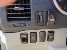
For your amusement, here is a photo of my "36 enable" switch in the dashboard (the one at the upper right):
 

Attachments

  • new-TV-wiring-Zombie-Switch.jpg
    new-TV-wiring-Zombie-Switch.jpg
    296.4 KB · Views: 2
Back
Top