I just installed a deye hybrid inverter and in the box is an item I can't find any info on. It is not described in the manual and I can't find any further info on the internet either. Presumably it is an antenna, but where to plug it in and what it is used for is not clear to me.
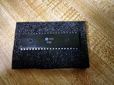
This is the picture of the item :
looking forward to any reactions.
View attachment 231907
This is the picture of the item :
looking forward to any reactions.
View attachment 231907