diy solar

diy solar

Deye inverter help please, parallel wiring issue

tnutt19

New Member
Joined
Dec 30, 2023
Messages
17
Location
Queen Creek, AZ
Hello everyone. I am knew to this forum but have read many post through the years. I have an issue that I cannot resolve and am hoping I can get some help.

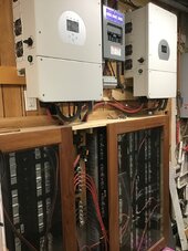
I recently completed having the solar installed on my home. System includes (4) Deye US version of the 8KW inverters, 62 500w panels, 4 powerwall batteries. For the first 5 weeks I have ran them as independent inverters without batteries in "selling first" mode and they have produced wonderfully. Now though I want my 4 powerwall batteries to be able to provide power if the grid goes down and also to provide power during Time of use. Here is where the issues occur.

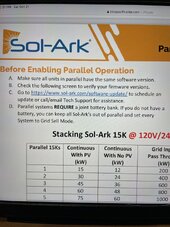
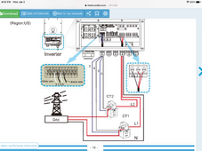
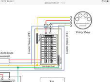
I installed two CT scanners and placed them between the main breaker and the city with arrows pointed toward inverters direction of flow. I connected all the inverters with the supplied cat 5 and changed them to be wires in parallel with the main inverter (master) receiving the feed from the (2) CT units and then each of the other 3 inverters set to 02, 03 and 04 in parallel mode. I selected lithium battery and have all turned on with the time of use set up as well.
On to the issue.
When I change the setting to "Zero Export to CT" and also select "Solar Sell" the power being generated by the solar panels completely drops off to almost nothing, somewhere in the range of .04kw. If I change back to "selling first" then the power the solar produced jump up back to normal. Basically for the life of me I cannot find out how to program them so that the batteries work properly with solar working with the batteries and parallel in zero export to CT with solar sell on working.

Any input as to what I am doing wrong or how to resolve?

If it helps, my goal is to allow the batteries to supply power during peak time and if grid goes down at any time. I do not want to supply battery power back to the grid but do want to supply solar power back to the grid.

Any help would be much appreciated. I have tried Deye customer support and they simply do not respond.

Thank you!
 
Slight clarification.
The issue is occurring when I switch to parallel mode. When inverters are not setup with a master and in slave mode they all work but as soon as I change to parallel mode so they all can work with the batteries then the solar production drops from 4-5kw to .04.
 
Placing CT sensors on incoming utility mains is to sense power flow to grid. This is typically done to prevent or limit selling to grid.

It allows your loads in main panel to be supplemented by inverter backfeed power but the CT sensor on utility line will not let inverter backfeed beyond what is consumed by your loads in main panel. You still need utility power present but can drive utility consumption to near zero if you have the inverter backfeed power to spare beyond battery charging and AC output loads on inverter.

Most common mistake is orientation of CT sensors so they are not measuring back feed to grid. Flipping the two sensor wires is same as routing utility wires through CT sensors in wrong direction. (i.e. you can fixed a position mistake by reversing just sensor output wires, instead of the tougher fix of flipping CT coil direction over the large grid lines).

If you have no loads drawing power in your main panel and CT's are blocking inverter from putting any export to grid, the back feed from inverter will be zero. In additions, if not charging and no external AC output loads on inverter output then total PV will be backed down to zero as there is no place to consume the PV power.

When inverter is setup to prevent grid back feed it also holds a safety margin in the ballpark of 5 amps to account for possible errors in CT sensing so it does not mistakenly allow some backfeed to grid. So don't expect backfeed to main panel will completely drive utilities consumption to zero.

If utility grid drops outs there will be no backfeed from inverter.
 
Last edited:
Thanks for the response this is very helpful. I am pretty sure I have the CT scanner installed correctly but am confirming now. I do have the inverters set to sell excess energy back to grid though as well.
I believe the issue I am having is setting up the inverters in parallel mode. When I change to not be in parallel they produce power but as soon as they are placed in parallel mode they don’t. I just flipped the leads from Ct scanners and they did reverse power load that represents the power I am feeding into the grid right now so I believe these were right which is good. I just need to solve the issue of parallel mode.
 
I am putting back in parallel and reversing Ct feed lines to see if that makes a difference starting just on two inverters. Hang tight
 
Playing with the CTs are certainly changing things up. The strange thing though is not all inverters are doing even near the same thing. I’m parallel they all should read from the CTs on the master inverter right? Battery reading is crazy right now with each showing no percentage and each doing it’s own thing but maybe that is becauseI just made the changes?
 
That was my next thought. Some show charging some show discharging and I think all should be doing the same thing. A reboot is a good idea.
 
4 inverter must be the same firmware, ask Deye to update. Only a master needs a CT. All a slave control by master.
 
I have a feeling firmware is not the same on all. I will reach out and ask them although they have not been very responsive. I cycled power and two came up saying they are out of phase so I corrected that and they appear to be working better now. I will see what happens over the next day and try to see if they can update my firmware for them.
Thank you all for the help.
 
Thank you this is super helpful. I will try them on WhatsApp after New Years.
Things are actually working better but I still think a firmware update is needed. The inverters sat for 30 months in my garage before I was able to put the project together. I’m sure firmware is outdated.
 
That is not important. Important is that they have the exact same version.
If they work well with the current FW - don't update as those carries with them other issues again...
 
Deye is the same as Sol Ark.
 

Attachments

  • 97258B4E-B0A3-4C90-B946-7EC4D4945453.jpeg
    97258B4E-B0A3-4C90-B946-7EC4D4945453.jpeg
    183.4 KB · Views: 13
They are still doing funny stuff, I think the firmware needs updated. For example when I put them back in sell mode and turn battery bank off they still show the battery bank and are trying to charge. I cycled power and still the same but no chance they can see the bank because I turned breakers off.
Sol-ark info is helpful too. Everything looks to be all setup correctly. For whatever reason they just aren’t working on parallel mode. Hopefully they respond back to me and I can get the issues resolved. Really want the batteries for time of use relief and back up for when grid goes down.
 
when you update a firmware,all 4 of inverse can communicate, the master will control everything, so only a master needs a CT.
just email Deye aks for update firmware.( I have same problems which 2 inverter parallel before,and Deye update firmware )
I have 2 Deye 8kw, 22kpv, 80kWh batteries.
 

Attachments

  • 938ABE1C-46FF-4E69-BE98-16041A3F5AF8.jpeg
    938ABE1C-46FF-4E69-BE98-16041A3F5AF8.jpeg
    154.2 KB · Views: 11
Last edited:
Awesome I’m thinking the update will solve my problems. Hopefully they get back to me soon so I can resolve.
Thanks for the help. I’ll report back so others may find the answers that are having similar issues.
 
Deye updated the firmware and now the inverters are all communicating properly and appear to be working right. The one issue I am having now is determining placement of my CT's and direction of flow. I have been messing around with locations for this and know I have this wrong which is showing incorrect numbers for load. Any input here would be helpful.

Please see image below. I actually just moved the white CT down to where it is now and am pretty sure I have it facing the wrong direction. Should I place both CT's on the incoming line above where the black one is and if so which direction should the arrows face? Otherwise I would have to use 4 CT's if I place below the breaker to accommodate this box and the external one.

1704319581829.png
 
Use one pair in Master inverter Only. a arrow point to grid.( grid in L1 and L2). Looks at your picture,your are doing right but move one down ( black one) be low a breakers arrow point to a breackper ( one ( white) at below breaker stay the sam)all arrow point to a breaker.
 

Attachments

  • 01A0FE1B-A947-42F0-8912-12D0B24E7BC5.png
    01A0FE1B-A947-42F0-8912-12D0B24E7BC5.png
    613.2 KB · Views: 12
  • C07FBCE2-E1A3-4CA5-954E-AF5C16BBAB3E.png
    C07FBCE2-E1A3-4CA5-954E-AF5C16BBAB3E.png
    303.3 KB · Views: 8
Last edited:
Helpful thank you. My concern is moving the Ct scanners down where the white one is won’t capture the secondary feed lines going to a different breaker that are on the right hand side, right?
Also Deye is saying that CT scanner should be within 10 meters of the inverter. This may be an issue for me as my main box is about 165 ft away. Thoughts on if this will be a problem?

Thanks for the help!
 
Back
Top