diy solar

diy solar

Deye Sun-12k-sg04lp3-eu weird Battery Discharge Behaviour when Battery Voltage is ABOVE Float/Absorbtion/Equalization Setting

silverstone

Solar Enthusiast
Joined
May 3, 2022
Messages
1,041
I got the system up and running approx. September 2023. Still a work in progress, but I have 2 x 1p16s batteries (in parallel) with JK BMS.

Deye is working in Voltage Control Mode for the Battery. IIRC on the Deye I set Float to 54.2VDC, Absorbtion to 55.0VDC and Equalization to 55.0VDC.

I have also a charger connected to the Batteries (in parallel), which I can control remotely using CANbus.

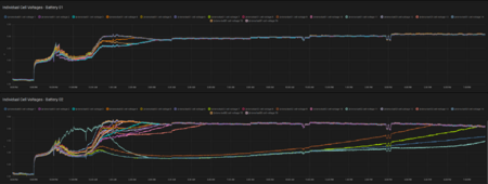
However, I noticed especially yesterday-today, when I am forcing a "top off" balance of all cells and leaving the pack voltage ABOVE Float/Absorbtion/Equalitation, today I have 56.0-56.1 VDC, that ALL the PV power gets completely ignored. I am doing this to force the cells to properly balance, as my second battery was all over the place:
1709492151449.png

I am using the Deye in "off-grid" mode (Load/Backup port only), and what I observe is that instead of taking PV power -> Load, what happens instead is Grid Power -> Charger -> Battery -> Inverter -> Load. Thus a lot of losses which I typically spare (if there is sun and I'm below Float/Absorbtion/Equalitation Voltage).

I'm not sure if the Deye is thinking ... "Battery is Overvoltage, I should discharge it" or what is going on exactly ...

At some point I was planning on using an ESP32 with https://github.com/klatremis/esphome-for-deye to control the Deye Voltage. But I don't think it's too good to keep changing the voltages settings, as this will IMHO wear out the flash memory of the Deye potentially very quickly.

Anybody experiencing something similar ? Is this a bug that was fixed in a later firmware update ? Or is this a "feature" ?
 
I cannot comment on your exact setup or issue, but in general, yes inverters can defenitely go in discharge mode when the actual system voltage exceeds the configured max battery voltage.
I had similair behavior with Victron and the Multiplus settings.

You force the top-off with your other connected charger so you get above the Deye voltage max settings? It makes sense it responds this way.
As an alternative, you could just place an active balancing board and forget your complicated setup with the second charger.
Or change the voltage. This topoff shouldn't need to happen so often (like every one to three months?) so I wouldn't worry about the eeprom.
The charger is needed to ensure the batteries never go too low. The inverter is NOT directly connected to the grid.

For now I think I have worked around the issue by setting the float voltage to 56.0 VDC.

A bit high for my taste but ...
 
Well, you can configure the BMS can't you? So make the balancing start at 3.4v or 3.35 or something, and lower the float voltage.
I think the float voltage is high if it is going to run like that, floating for complete summers. But it will still work.

Your use case is of course not as intended, because you would just use the AC grid port of the Deye for that.
And it also lets you set minimum levels for the battery.
I had the balancing set too low previously and it CREATES an unbalance if it's like that. It needs to be in the steep part of the voltage vs soc characteristic, as Andy from Off Grid Garage points out. I have it set at 3.45V.

The alternative is to lower float voltage on both inverter and charger, only do absorbtion / equalization on the inverter, and with some closed-loop control for the charger make it run in Constant Current mode just at say INVERTER_FLOAT_VOLTAGE - 0.1V (to account for tolerances) and then switch immediately to Constant Voltage. But I'm not there yet ...
 
I wouldn't expect to see imbalance quickly, only after a while.

Anyway, I would just put active balancers on the battery and simplify the whole setup. That will save you lots of time.
Anytime when the battery is going low or high, the active balancers will kick in.
 
Try to build this ESP32 communication board between JK BMS and Inverter.

You will have SOC, Float, Bulk voltages, charge and discharge current set in inverter by interface. Sleeper85 did a very nice project and implement useful function to the code.
One function is that the bulk voltage is keep until the balance function of BMS is OFF, triggered when delta cell voltage is dropping below your BMS set voltage. This function ensure that the voltage is not keeped more than needed and your cells are balanced. If you want, you have the option of manually keep the bulk voltage as long as you like. If you don't have Homme Assistant you can use web page to change the settings.
Looks interesting, but it says in the notes:
>> Note: This code support only one BMS connection per inverter and should work with inverters that support the CAN bus protocol shown in the table below.I'm only testing it with my Deye SUN-6K-SG03-LP1-EU inverter.


Otherwise it could be an interesting option indeed.

Right now I'm using just for remote monitoring
But I mean, in theory, everything is possible.

I could also use syssi ESPHome-JK-BMS for every battery, gather the data and send it to MQTT, forward these to InfluxDB, then modify what Sleeper85 did into a multi-battery BMS (more like a JK BMS emulator) which is just fetching the values from the different BMS from a database.

Granted I would lose some features though like actively control the BMS, but I could at least control the inverter ...
 
Looks interesting, but it says in the notes:
>> Note: This code support only one BMS connection per inverter and should work with inverters that support the CAN bus protocol shown in the table below.I'm only testing it with my Deye SUN-6K-SG03-LP1-EU inverter.

Yes, it only can communicate with one, but i understand that you have 2 batteries in parallel with JK BMS. You can choose one BMS to communicate with inverter and set in the other one identical settings. Batteries will have almost same SOC while charging and discharging. If you have DIY battery and they have the same cappacity cells you can reorganise the batteries with 2 cells in parallels (16S 2P)) and use one BMS (you will stress more the BMS as you will draw double current pass trough on BMS)

I could also use syssi ESPHome-JK-BMS for every battery, gather the data and send it to MQTT, forward these to InfluxDB, then modify what Sleeper85 did into a multi-battery BMS (more like a JK BMS emulator) which is just fetching the values from the different BMS from a database.

I have used Syssi code at the begining with Home A. and was working fine but i find Sleeper85 code more suitabe for me as i only have one BMS. I would say to start with Slipper85 first, test with one BMS and then go forward.
Choose the right ESP32 as not all version have CAN support.
 
Back
Top