diy solar

diy solar

DGJBD Bluetooth BMS - a short review

My only thought is that the wires are backwards. I have no idea if they are polarity sensitive.
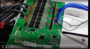
Huh... Didn't think of that! Lol... I'll go swap them and report back.
Edit: tried reversing the probe leads. Didn't work...
 
Last edited:
Those should be a resistive element, so polarity won't matter .... and it appears you are getting a temperature reading .... is it accurate?

That's a different version of the App than I have .... do you have a means of turning the battery on and off with that version of the App? If so, I would try turning if off and back on.
 
OK, solved. The exterior temp sensor is faulty. Not only broken, but when hard wired and soldered to the board it still does not read out correct. I was able to override it in a way I hadn't discovered. Temp sensor 1 was reading - 30 and number two was accurate. Obviously one sensor is on the board and one is that probe. So I changed Number 1 to read +10 C. and bingo. As the probe receiver was damaged and fell off the board, it appears soldering it direct didn't work either...
Very interesting!
Anyway, BMS is functioning now (partially) , and a replacement is on the way.
Those should be a resistive element, so polarity won't matter .... and it appears you are getting a temperature reading .... is it accurate?

That's a different version of the App than I have .... do you have a means of turning the battery on and off with that version of the App? If so, I would try turning if off and back on.

The temp shown on the dashboard of the app is always going to be from the sensor with the highest value. It's probably showing the temperature from the internal sensor on the BMS. If you "click" on the temp it should bring up the temperature of both sensors.
 
The temp shown on the dashboard of the app is always going to be from the sensor with the highest value. It's probably showing the temperature from the internal sensor on the BMS. If you "click" on the temp it should bring up the temperature of both sensors.
EXACTLY! I'd been through every setting and menu conceivable... But didn't actually click the temperature read g on the dashboard. When one said - 30, I realized that changing it to a positive number was mentioned in the Overkill instructions. Did it and it worked!
YAY... Thanks. Loving this forum!
 
Has anyone tried using the hardware on/off switch on this BMS. I see that the Overkill Solar version has an actual 2 pin header soldered next to the Bluetooth and balance headers. And their documentation mentions adding such a switch. My BMS doesn’t have the header but it has 2 spots on the PCB that are labeled on/off or something like that.

I was going to put a high current battery cutoff switch on my battery box, but if I can just use a small low current switch instead I’d prefer that option. I’ll have a high current breaker I can use as a cutoff downstream in my system instead.

Also curious if anyone has tried disassembling their BMS. I need to pull the aluminum plate off to get access to the on/off pins so I can solder a header on there. Just wondering if the thermal paste between the FET’s and the aluminum plate releases easily and how much fiddling it will take to touch up the paste and get it back together.

-uberpixel
 

Attachments

  • Screenshot 2021-03-14 083355.jpg
    Screenshot 2021-03-14 083355.jpg
    71.7 KB · Views: 35
Has anyone tried using the hardware on/off switch on this BMS. I see that the Overkill Solar version has an actual 2 pin header soldered next to the Bluetooth and balance headers. And their documentation mentions adding such a switch. My BMS doesn’t have the header but it has 2 spots on the PCB that are labeled on/off or something like that.

I was going to put a high current battery cutoff switch on my battery box, but if I can just use a small low current switch instead I’d prefer that option. I’ll have a high current breaker I can use as a cutoff downstream in my system instead.

Also curious if anyone has tried disassembling their BMS. I need to pull the aluminum plate off to get access to the on/off pins so I can solder a header on there. Just wondering if the thermal paste between the FET’s and the aluminum plate releases easily and how much fiddling it will take to touch up the paste and get it back together.

-uberpixel
Or you can use the software On / Off buttons in the app.
 
Or you can use the software On / Off buttons in the app.
Good suggestion. I kind of like having a physical switch so I don’t have to use my phone to turn off the battery. Maybe the software switch would be adequate for my application.

Not sure I like relying on software for this function, but you could argue that neither option is a true cutoff. At least the physical switch would bypass the Bluetooth/phone requirement.

-uberpixel
 
Or you can use the software On / Off buttons in the app.
Even with it off via the app, how much power is still consumed? It has to keep somewhat powered up so you can turn it back on via the ap right? I am planning for RV usage. 2 weeks "off" won't drain the battery will it?
 
Even with it off via the app, how much power is still consumed? It has to keep somewhat powered up so you can turn it back on via the ap right? I am planning for RV usage. 2 weeks "off" won't drain the battery will it?
Should be ok.

Q: What is the quiescent current? What can I do for long-term storage?
A: The quiescent current is as follows: (this was measured on a 4 cell BMS)
● 5.5 milliamps with everything off, when the BMS is active, but no bluetooth.
● 15 milliamps with the bluetooth active (after about 10 seconds it drops to 0.8 milliamps.
Reconnecting it wakes it up again).
0.8 milliamps when the BMS is inactive.
So, assuming your battery setup is 100 amp hours, the BMS would run for 17 years.
This proves that the BMS can be connected for long periods of time without any fear of it draining the battery.
Unplugging the balance connector would ensure complete shutdown
NOTE: The cell’s self-discharge rate will always cause the battery to drain over time, which may be several percent per month. This is simple chemistry and physics; there’s nothing that you or the BMS can do to avoid the battery cells from self-discharging over time, other than to occasionally top up the batteries.
Taken from https://github.com/FurTrader/OverkillSolarBMS/raw/master/Overkill_Solar_BMS_Instruction_Manual.pdf

Page 28
 
Here is that Video I mentioned... Had a YouTube issue, so it didn't post right away. I also re-rendered it this morning with an adjustment.
 
Here is that Video I mentioned... Had a YouTube issue, so it didn't post right away. I also re-rendered it this morning with an adjustment.
Thanks for your contribution but it is a bit difficult to watch the video as the camera moves around a lot. Maybe a static mount for the camera will help in this respect. I would very much like to watch the video without this issue. Regards.
 
I'd highly recommend using a gimball. This movement is pretty annoying. Also, adjust sound in post, its hard to understand.

As for the 'fix': You've wired the sensor to the supporting pins of the plug, which basicly don't do anything else than supporting the connector.
The actual pins are the 2 on the back of the connector

If you're in doubt of the sensor: It's just a regular 10kohm NTC


1615925195573.png
 
I'd highly recommend using a gimball. This movement is pretty annoying. Also, adjust sound in post, its hard to understand.

As for the 'fix': You've wired the sensor to the supporting pins of the plug, which basicly don't do anything else than supporting the connector.
The actual pins are the 2 on the back of the connector

If you're in doubt of the sensor: It's just a regular 10kohm NTC


View attachment 41203
Excellent advice, thank you. Thanks for the critique on the video and the soldering info too. You can't get better without out someone pointing out mistakes, faults and ways to improve. It's appreciated!
I added this warning to the details of the video! Haha...

"Edit & Update: Caution, this video may make you sea-sick! Lol... This was a casual video shot with my phone. New camera and gimbal are in the works. I had people asking for info in it, so I'll keep it up. People, wiser than I, have commented my solder points were incorrect. As I still have the bms, I'll de-solder, correct and update. "
 
Last edited:
Just to answer my own questions in case anyone is curious...

Has anyone tried using the hardware on/off switch on this BMS. I see that the Overkill Solar version has an actual 2 pin header soldered next to the Bluetooth and balance headers. And their documentation mentions adding such a switch. My BMS doesn’t have the header but it has 2 spots on the PCB that are labeled on/off or something like that.
This works. After removing the aluminum plates, I soldered a 2 pin header to the board, hooked up a switch and enabled the “Switch” functionality in the BMS via Bluetooth. It seems some resellers have a version of this BMS where they chose to save $0.03 and leave the switch header off (like mine), but the rest of the hardware and software support the functionality.
Also curious if anyone has tried disassembling their BMS. I need to pull the aluminum plate off to get access to the on/off pins so I can solder a header on there. Just wondering if the thermal paste between the FET’s and the aluminum plate releases easily and how much fiddling it will take to touch up the paste and get it back together.
This was no big deal (thanks to SoundinSpirit for some reassuring advice). I was worried that the “paste” might have hardened making it difficult to remove, but it’s actually not paste but some sort of foam tape. Makes me question its efficacy as a thermal conductor, but whatever. The tape did peel partially off the plate when one section stuck to the FET, but it was easy to reposition and put it all back together.

One quirk is that with the hardware switch “off” it appears that the load side is off but the charging side is still active, whereas using the software switch via the app you can turn off both charge and load sides. I think the charge side can be activated via toggle in the app, but I don’t think that has effect on the hardware switch behavior.

-uberpixel
 
Is there a recent link to the JBD BMS on Alibaba? The link at the start of the thread takes me to a 60a Scooter BMS and I'm looking for a JBD 150A unit (2x) TIA
 
Is there a recent link to the JBD BMS on Alibaba? The link at the start of the thread takes me to a 60a Scooter BMS and I'm looking for a JBD 150A unit (2x) TIA

I ordered mine from this place and it was about 3-4 weeks to receive them in the US. The 120A version comes with three wires on each side.

 
Is there a recent link to the JBD BMS on Alibaba? The link at the start of the thread takes me to a 60a Scooter BMS and I'm looking for a JBD 150A unit (2x) TIA
The link that I posted still works. Follow the link and on the landing page you will see a block on the right hand side and in the block under ‘Gold supplier’ click on the company name. This will take you to the suppliers website. Now at the top of the page select ‘Products‘ then ’BMS’ on the dropdown menu. If you are still uncertain you can contact the supplier as well fro that page. They are very good at replying to enquiries.
 
I ordered mine from this place and it was about 3-4 weeks to receive them in the US. The 120A version comes with three wires on each side.

Is there a recent link to the JBD BMS on Alibaba? The link at the start of the thread takes me to a 60a Scooter BMS and I'm looking for a JBD 150A unit (2x) TIA

Hi I use these guys - generally arrives within 10 days to Australia. They currently have 150amp models as well. Best is to go to the site and open a chat - I find the format horrible on my iPad. Can’t find anything
 
Thanks Dodger - I use them as well. Keep well down under.
 

diy solar

diy solar
Back
Top