diy solar

diy solar

DIY BMS design and reflection

Well, I'll do tests IRL when I have the MOSFET on hand and if I can't make them conduct then I'll remove that part of the circuit I guess.

That's a good way to move forward. Fewer parts means less can go wrong. Especially if these parts serve little purpose.

Regarding your statement: "The thing is we don't apply a voltage to the gate, the Miller effect isn't at play here." I don't believe that's true. A voltage is applied to the gate via the internal capacitor divider. This voltage turns the fet on (given specific conditions). For the fet to turn on the Miller capacitor has to be active. There's no way around it. I'll state it again, it takes a lot of energy to charge the Miller capacitor.
 
The Miller capacitance isn't real, it's a consequence of having Vds changing by a large amount (by a ratio equal to the gain of the MOSFET) as you change Vgs, multiplying the apparent Cgd capacitance by said gain. But here we change Vds, and Vgs changes as a result of the capacitive divider, I don't see how the Miller effect would work here (Vs would need to change to have any kind of Miller effect but that's not the case here since it's our GND of course, it stays at 0 V).
 
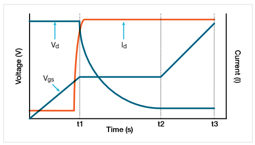
That's correct Vds changes by a large amount. It changes from battery voltage to zero volts. Since the source is grounded, the drain voltage drops to ground when the fet is fully on. That would be t2 on the graph. The time between t1 and t2 is the Miller plateau. It's the time it takes for the drain voltage to drop to approximately zero volts.

fig-2.png
 
Yes but that's only the case when you control the MOSFET via Vgs, but here we're talking about the case where the gate is basically unconnected (or there's a high value resistor between the gate and the source) and you apply a voltage across the drain and source (so it changes for 0 to battery voltage actually). I can assure you for a start that Vd will not look like on your graph (unless we zoom a lot of course and we are in the ns domain), it'll basically be a brick wall if we keep the same scale as in your graph. It is this big change in a short time that can turn on the MOSFET. Then, once the MOSFET turns on Vds will drop of course; but I don't care about that, the MOSFET has turned on at this point, and that's what I try to prevent.

But as said, I'll make real tests with real MOSFETs once I make the order to make the prototypes, andof course I'll record Vds and Vgs on the oscilloscope to see what happens, then we will be 100 % sure ;)

NB: sorry for the reply delay, I wasn't home this week-end.
I understand the theory: a voltage step function provides a charge to the gate (by way of the fet two capacitors). The gate charge is enough to turn the fet on.

Let's look at an example.
Vbat = 48V
Cgd = 33 pF
Cgs = 500 pF

Due to the capacitive divider, the voltage at the gate is about 3V. That means Vgd = -45V (negative voltage polarity when referenced from gate). With the source connected to ground, Vd = 0V when the fet is on. As the drain drops to 0V (which I define as the fet being on), the gate-drain capacitor must discharge the -45V and then charge to about the threshold voltage which is opposite polarity. All this energy must come from the charge on Cgs. That's been my concern. There's not enough energy to accomplish this.
 
Ok, I see, you're talking about the time slice that comes after, but I'm talking about what comes just before.

Taking both into account my guess is that the MOSFET will be partially ON for a short time before opening again. But I'll see what happens for real anyway ;)
 
I see where you're coming from. However if the drain voltage gets to zero volts (which is my definition of the fet turning on) then it's impossible for the gate-drain voltage to have the initial -45V from battery getting switched on. The capacitor Cgd must first discharge this negative voltage and then charge to the threshold voltage. This process takes time. We know changing capacitor voltage is not instantaneous.
It changes by dV = I * dt/C

I'm looking forward to see your test results. You probably don't need the specific MOSFETs your going to use for preliminary results. My guess you won't see anything significant, if anything at all.
 
Looked at the BMS schematics. Are you by chance a shareholder in Precision Resistor...??? If not you might want to consider resistor networks since most of these 0.05%ers seem to be used ratiometrically anyway.
 
Cheapest 10k ohm, 0.05% matching network I found was $3.70 each, $2.44 for 100.
What can you find?


I've used 0.1% parts, tried to count on tracking of values. Mostly 10 ppm to 25 ppm/degree.

Checking DigiKey for 0603 sizes, 10k ohm as an example,
cheapest 0.1% I find is $0.23 each, $0.075 in strip of 100. That's 50 ppm/degree.
For $0.67 each, $0.38 in strip of 100, you get 10 ppm/degree

Cheapest 0.05% is $2.33, $1.58 in strip of 100. 5 ppm/degree.


I've used other value of same family part hoping to get value tracking (ratio having better ppm per degree.)
Have to watch out for self-heating, can't run one hotter than the other and get as good tracking.
Also, that ppm isn't a straight line from minimum to maximum temperature. It follows an "S" curve, because it is tuned to stay as close to nominal value as possible. A part with 50 ppm spec and 100 degree operating range would span 5000 ppm (0.5%), or +/- 0.25% from nominal. It could be nominal at 25 degree temperature, and +0.25% at 50 degrees.

For ratio of similar values I've put two or three of same part in series or in parallel.
 
Looked at the BMS schematics. Are you by chance a shareholder in Precision Resistor...??? If not you might want to consider resistor networks since most of these 0.05%ers seem to be used ratiometrically anyway.

I already looked into networks but they are more expensive and their availability is not great either. But thanks for the suggestion ;)


Cheapest 10k ohm, 0.05% matching network I found was $3.70 each, $2.44 for 100.
What can you find?


I've used 0.1% parts, tried to count on tracking of values. Mostly 10 ppm to 25 ppm/degree.

Checking DigiKey for 0603 sizes, 10k ohm as an example,
cheapest 0.1% I find is $0.23 each, $0.075 in strip of 100. That's 50 ppm/degree.
For $0.67 each, $0.38 in strip of 100, you get 10 ppm/degree

Cheapest 0.05% is $2.33, $1.58 in strip of 100. 5 ppm/degree.


I've used other value of same family part hoping to get value tracking (ratio having better ppm per degree.)
Have to watch out for self-heating, can't run one hotter than the other and get as good tracking.
Also, that ppm isn't a straight line from minimum to maximum temperature. It follows an "S" curve, because it is tuned to stay as close to nominal value as possible. A part with 50 ppm spec and 100 degree operating range would span 5000 ppm (0.5%), or +/- 0.25% from nominal. It could be nominal at 25 degree temperature, and +0.25% at 50 degrees.

For ratio of similar values I've put two or three of same part in series or in parallel.

Tempco isn't my biggest error source for the 100 k resistors so I've selected 50 ppm ones for those. However most of the 10 k ones are used to generate reference voltages so here I selected 10 ppm ones. Same for the 2 k and 82 k ones as they are used in the very sensitive current shunt amplifier, they are 10 ppm too. In total I have around 12 € of 0.05 % resistors on the BMS board; relatively expensive but it's the best I could come up with and it's not too bad either.

Another problem with networks is the routing; it would be fine for the 100 k ones but for all the other ones it would makes things very complicated (and it was already a big PITA to route that PCB ?).
 
I already looked into networks but they are more expensive and their availability is not great either. But thanks for the suggestion ;)


Tempco isn't my biggest error source for the 100 k resistors so I've selected 50 ppm ones for those. However most of the 10 k ones are used to generate reference voltages so here I selected 10 ppm ones. Same for the 2 k and 82 k ones as they are used in the very sensitive current shunt amplifier, they are 10 ppm too. In total I have around 12 € of 0.05 % resistors on the BMS board; relatively expensive but it's the best I could come up with and it's not too bad either.

Another problem with networks is the routing; it would be fine for the 100 k ones but for all the other ones it would makes things very complicated (and it was already a big PITA to route that PCB ?).
I mean ordinary 1% resistor networks since
 
.... err post disappeared a little early - again, I meant ordinary 1% networks since normally these are very well matched on the same network. Also it would probably pay to be a little more creative in say, using the voltage reference as input to calibrate the ADC and not care too much for the actual resistor division ratio.
 
1 % is far to wide here, and yes, they are typically well matched but there's no guarantee, I can't rely on typical values.

The ADC will be calibrated at the same time than testing is done on a bed of nails jig. In any case, the ADC calibration doesn't correct a bad resistor ratio (well, it could correct one, but here I have dozens of ratios). And for the 100 k ones they must be well matched mainly because of the common voltage they will see.
 
Well you have a point there of course. I have been working on my own BMS when I saw this one. I have been trying to rid my design from all precision components except for the ADCs so that is why I kind of got in a bind seeing this exorbitant number of .05% resistors :). I am simply using an isolated ADC for each analog input on two I2C busses. I think a 16-bit adc with internal ref plus i2c isolator is probably not much more expensive than a single .05% resistor... Compared to the BMS presented here I also have some different requirements. Meant for a boat, I do e.g. NOT want the BMS to EVER disconnect power without my approval. More warnings and lead time to solve problems, plus possible automatic start of genset is then necessary. Moreover I have board computers running 24/7 and will use a simple serial link to one of those, information will be presented in an application and on an intranet web page. Oh, and I am a bare metal programmer... so when I see Arduino ... brrr... Anyway, very interested to see how this project develops including design ideas!!
 
Well you have a point there of course. I have been working on my own BMS when I saw this one. I have been trying to rid my design from all precision components except for the ADCs so that is why I kind of got in a bind seeing this exorbitant number of .05% resistors :). I am simply using an isolated ADC for each analog input on two I2C busses. I think a 16-bit adc with internal ref plus i2c isolator is probably not much more expensive than a single .05% resistor... Compared to the BMS presented here I also have some different requirements. Meant for a boat, I do e.g. NOT want the BMS to EVER disconnect power without my approval. More warnings and lead time to solve problems, plus possible automatic start of genset is then necessary. Moreover I have board computers running 24/7 and will use a simple serial link to one of those, information will be presented in an application and on an intranet web page. Oh, and I am a bare metal programmer... so when I see Arduino ... brrr... Anyway, very interested to see how this project develops including design ideas!!
love this concept!

writing firmware is fun for me and i too am looking into DIY bms for more flexibility. (land based use) this thread provides me with lots of inspiration to study to understand and to integrate aspects into my own experiment.

interesting discussion here about front end voltage measurements. thank you all!
 
Well you have a point there of course. I have been working on my own BMS when I saw this one. I have been trying to rid my design from all precision components except for the ADCs so that is why I kind of got in a bind seeing this exorbitant number of .05% resistors :).

Oh you definitely can, there's a lot of different topologies to achieve the same thing ;)

I am simply using an isolated ADC for each analog input on two I2C busses. I think a 16-bit adc with internal ref plus i2c isolator is probably not much more expensive than a single .05% resistor...

I'm pretty sure that's not possible (unless maybe you compare a chinese ADC with the most expensive 0.05 % resistor you can find). But I'm curious to see ? Do you have a thread describing your project?

Compared to the BMS presented here I also have some different requirements. Meant for a boat, I do e.g. NOT want the BMS to EVER disconnect power without my approval. More warnings and lead time to solve problems, plus possible automatic start of genset is then necessary.

I see, that makes sense.

Moreover I have board computers running 24/7 and will use a simple serial link to one of those, information will be presented in an application and on an intranet web page.

Same here, the HMI board I'm currently designing is optional, the main UI will be a self contained web app ;)

Oh, and I am a bare metal programmer... so when I see Arduino ... brrr...

Don't worry, I am too ? I only use arduino because it's a convenient platform but for this project I'll not use the arduino lib as it's slow, bloated and most of all, it can't be trusted.

writing firmware is fun for me and i too am looking into DIY bms for more flexibility. (land based use) this thread provides me with lots of inspiration to study to understand and to integrate aspects into my own experiment.

interesting discussion here about front end voltage measurements. thank you all!

Yep, ideas exchange is great ;)

There's a lot more discussion about the front end in the older pages of this thread if you didn't read them already.

NB: I still need to correct something on the current version of it actually, do not use as-is as it'll not work properly. More info about the exact problem here ;)
 
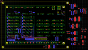
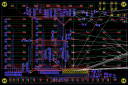
Tonight I've continued the routing:

HMIB_PCB_Layout.png

The left half and the bottom are now fully routed ?


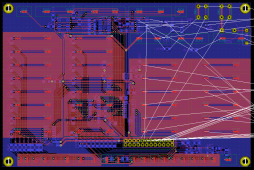
I also did the copper planes:

HMIB_PCB_Layout_2.png

I guess you can see why I hide them most of the time when I route the board...
 
I'm pretty sure that's not possible (unless maybe you compare a chinese ADC with the most expensive 0.05 % resistor you can find). But I'm curious to see ? Do you have a thread describing your project?
Sorry, no thread or site... Too busy on various project to accurately describe and update. I am sure you have spent quite some time on this forum. My BMS needs to be ready in two months... BTW I checked pricing and all silicon seems to have exploded. I have bunch of old ADS1211U's that are now over $35/pc?? Many items simply sold out with lead times >52 (!!!) weeks. Never knew you could speculate with integrated circuits, until now...
 
Back
Top