diy solar

diy solar

DIY Coulomb counter for LiFePO4

BjornM

MacGyver's apprentice
Joined
Oct 7, 2023
Messages
157
Location
Sweden
Has any of you designed and built a Coulomb counter for LiFePO4 batteries, to keep track of SOC?

My current lead acid setup already has a voltage and current sensor connected to an Arduino with a screen. Soon I'll switch to LFP, so why not take some time and implement a SOC monitor in software, just because it is fun. See if I can match the Coulomb counter in the BMS. Just need to figure out a good algorithm for LiFePO4.

A very simplified model is just energy in, minus energy out, minus losses (how much?), minus self discharge (how much?), plus keeping track of the upper and lower voltage tail ends and then resetting the SOC to 100%/0% when those happen.
 
Last edited:
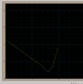
I have one I programmed for my use I measure battery volts and battery amps every 10 seconds and multiply the two to get watts then multiply that by a fraction to get a number to get watts per hour that fraction is dependent on your sample rate then add that to the total watts the battery will hold I reset to the total watts the battery will hold at the full charge voltage of the battery. I use a different fraction on charge than I use on discharge due to charge efficiency on LiFePO4 I use 94% of the discharge fraction I do not factor in self-discharge. My display is Kwh, not SOC.

Screenshot from 2023-10-17 09-46-34.png
the display is 70 to 80 kWh and the X is one hour per division.
 
The outlined algorithm/model seems like a good direction.

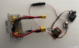
Tinkered with an NAU7802 ADC to measure voltage drop with an "AiLi" shunt resistor on the low side that was something like 50mV 250A, and an INA219 to measure positive side voltage

here's a photo of the thing. it was set up with XT60 connectors as a passthrough for testing. it kind of worked, but getting the zero offset to be stable was a challenge.

1697556679231.png

eager to discuss any DIY coulomb meter stuff you might experiment with ? good luck
 
@labeeman interesting! Is 10s resolution enough

I seem to have issues with my JBD BMS keeping track of SOC when I get a lot of sudden peaks of charge/discharge? Was wondering if the Victron Smart Shunt would be better, but no idea how frequently either of those devices samples the power.

@curiouscarbon interesting to hear more about how / where you used the INA219 - I just looked at the spec sheet and it referred to 26V?
 
Columb counter for LFP cells is pretty easy due to high efficiency on charge and discharge current from battery. For typical DIY setups the discharge and charging rates are less than 0.2 C(A) where the charge and discharge efficiency is better than 99%.

Biggest source of error is accuracy of current measurement over a wide dynamic range of currents. Try measuring a AA battery voltage with your DVM on 500vdc scale. Similar issue with current measurements.

Other issue with small bi-directional currents is DC offset of amplifying op amp from current shunt. At low currents the DC offset makes a significant error in actual current measured. Small current discharge can look like charging and vice-versa. There are chopping-self zero'ing op amps that compensate op amp DC offset. Typical op amp has a 1 to 2 mVdc offset uncertainty. This is amplified by the gain setting of op amp. Output of a 500 amp/50 mV shunt for 1 amp of current is 100 microvolts.

Many cheap BMS's just zero out current registering when current drops below an amp or two to avoid this incorrect tally summation into Columb counter.

Battery monitor must also have a very low frequency low pass averaging filter to remove the 120 Hz ripple current from a 60 Hz sinewave inverter DC current profile. Typically a 1 to 2 Hz low frequency pass average filter is used. A high sampling rate microcontroller with software averaging can also be used to average out the ripple current.
 
Typical op amp has a 1 to 2 mVdc offset uncertainty. This is amplified by the gain setting of op amp. Output of a 500 amp/50 mV shunt for 1 amp of current is 100 microvolts.
Hmmm, so if there is 1mV uncertainty, then one can't measure less than +/- 10A with 500A/50mV shunt accurately. Could a solution be to have a more sensitive shunt?
 
INA219 - I just looked at the spec sheet and it referred to 26V?
only could use it with 4 LFP cells in series. 8 LFP series would go up to 29.2V, exceeding the rating. which limits the applicability of this chip.

tried sampling a few seconds worth of the ADC to average for zero offset calibration (a few hundred samples), but it was still inconsistent and exhibiting errors of an amp or more. the goal was like 100 milliamp resolution up to 100-200 ampere, so still like one order magnitude off.

never tried temperature compensation. or capacitors to filter. unshielded wires probably didn't help either.

the sample rate was pretty high, like 100-200 Hz if memory serves, to mitigate AC ripple/aliasing artifacts. just follow the wave and average out, was the thought.

eventually went with a victron smartshunt because my DIY way was too fickle
 
@labeeman interesting! Is 10s resolution enough

I seem to have issues with my JBD BMS keeping track of SOC when I get a lot of sudden peaks of charge/discharge? Was wondering if the Victron Smart Shunt would be better, but no idea how frequently either of those devices samples the power.

@curiouscarbon interesting to hear more about how / where you used the INA219 - I just looked at the spec sheet and it referred to 26V?
You have to put input filtering on the current measuring device to average out the spikes.
 
I have one I programmed for my use I measure battery volts and battery amps every 10 seconds and multiply the two to get watts then multiply that by a fraction to get a number to get watts per hour that fraction is dependent on your sample rate then add that to the total watts the battery will hold I reset to the total watts the battery will hold at the full charge voltage of the battery. I use a different fraction on charge than I use on discharge due to charge efficiency on LiFePO4 I use 94% of the discharge fraction I do not factor in self-discharge. My display is Kwh, not SOC.

View attachment 172689
the display is 70 to 80 kWh and the X is one hour per division.

Cool project. Have your tried to increase the sample rate, so you catch transient power draws better? Or does it work well enough as is?
 
The outlined algorithm/model seems like a good direction.

Tinkered with an NAU7802 ADC to measure voltage drop with an "AiLi" shunt resistor on the low side that was something like 50mV 250A, and an INA219 to measure positive side voltage

here's a photo of the thing. it was set up with XT60 connectors as a passthrough for testing. it kind of worked, but getting the zero offset to be stable was a challenge.

View attachment 172703

eager to discuss any DIY coulomb meter stuff you might experiment with ? good luck

I'm using a INA226 over a current shunt, which almost identical to your INA219. I read at 4 Hz (four samples per second). And I have two such shunts, one for the charger and one for the power inverter, so it is easy to see incoming and outgoing current at the same time.

Unknowns at this point are roundtrip efficiency and self discharge rate. I will log all samples on an SD card, and eventually I will have a large enough dataset that I can calculate those. I'll keep you updated.
 
Cool project. Have your tried to increase the sample rate, so you catch transient power draws better? Or does it work well enough as is?
It works well as is, I have tried to increase the sample rate but I sample by way of either net and cannot get it faster because on my setup I get a 6-second delay sometimes. The computer is 200 feet from the sensors and runs Mint I use a command script. I only get a 1 to 20-watt error after discharging 20kWh
 
Last edited:
I've experimented with the INA229 but during that previous period when they were in short supply I purchased a few from an overseas supplier and they kept failing even though they were never subjected to anywhere near the max high side voltage. More recently was able to find them in stock from a more reputable supplier, Mouser or DigiKey. Hoping the results are better this time.
 
Columb counter for LFP cells is pretty easy due to high efficiency on charge and discharge current from battery. For typical DIY setups the discharge and charging rates are less than 0.2 C(A) where the charge and discharge efficiency is better than 99%.

Biggest source of error is accuracy of current measurement over a wide dynamic range of currents. Try measuring a AA battery voltage with your DVM on 500vdc scale. Similar issue with current measurements.

Other issue with small bi-directional currents is DC offset of amplifying op amp from current shunt. At low currents the DC offset makes a significant error in actual current measured. Small current discharge can look like charging and vice-versa. There are chopping-self zero'ing op amps that compensate op amp DC offset. Typical op amp has a 1 to 2 mVdc offset uncertainty. This is amplified by the gain setting of op amp. Output of a 500 amp/50 mV shunt for 1 amp of current is 100 microvolts.

Many cheap BMS's just zero out current registering when current drops below an amp or two to avoid this incorrect tally summation into Columb counter.

Battery monitor must also have a very low frequency low pass averaging filter to remove the 120 Hz ripple current from a 60 Hz sinewave inverter DC current profile. Typically a 1 to 2 Hz low frequency pass average filter is used. A high sampling rate microcontroller with software averaging can also be used to average out the ripple current.
Thanks for the info. I'll be using a INA226 on a 200A/75mV shunt. It has a 2.5 uV shunt measurement resolution (which over this shunt equals +/- 1.5 mA. But that's just the resolution, then you have OP-amp gain errors, ADC errors, offset errors, etc. I would guess it has an accuracy of around +/-40 mA, which for my 24 V system is +/- 1 W, which is more than enough for this application.

Re a low pass filter: If I skip such a filter, I imagine that the measurements average out over time. Sometime sampled at peaks, sometimes at valleys, etc. My sample rate is 4 Hz.

 
Re a low pass filter: If I skip such a filter, I imagine that the measurements average out over time. Sometime sampled at peaks, sometimes at valleys, etc. My sample rate is 4 Hz.
INA226 allows you to set the internal high sampling conversion rate with sample averaging. You need some input R-C analog filtering to avoid transients from corrupting sigma-delta ADC conversions.

You should select CT rate and averaging close to integers of 120 Hz period using the averaging to attenuate the 120 Hz ripple current.
The sample rate is around 500 kHz, so I wouldn't worry about the effects of 120 Hz ripple currents. On the datasheet of INA226, section "7.4.2 Filtering and Input Considerations", they do indeed recommend a low pass input filter, but for a cut off frequency of around 10 kHz. This would reject noise/signals close to the sample rate to improve sampling accuracy.
 
Back
Top