krby
Solar Enthusiast
Sorry for the long post, I think the background is important.
In July, I put together an over spec'd DIY UPS for my home network rack in the garage.

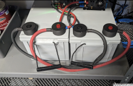
This setup is what's called a "double conversion UPS". It's running the inverter all the time. There is no transfer time when the power goes out. I had the inverter already (600W IAMS pure sine wave, on the right). So I bought the 12V AGM deep cycle batteries and an RV converter charger (a PowerMax 55A). The idea is that the converter/charger does AC/DC all the time, it will charge the batteries and the float them at about 13.5V while providing enough current for the inverter to run the load. My load is no more than about 250W, but ends up being about 120W most of the time and 60W if turn off the NAS.
One feature I lost by moving from a consumer UPS to this is the "notify gear to shut down via USB". So I dug into that recently and put together an Arduino with an AC detection board. The Arduino acts like a USB HID Power Device to a computer, reporting AC avail/unavailable. My NAS can then read that like it could from my consumer UPS and I've got it setup to shut down 5min after the AC power goes away on the UPS input. I stuffed the Arduino inside the case of the converter/charger on the left.
The reason for this post:
My Arduino right now only AC present/missing detection. But I could wire up and write code to handle voltage and current monitoring, LVC, etc. I've been thinking what I'd really like is a single "box" that is the converter/charger + inverter + the arduino for UPS monitoring via USB, but could also to LVC and other things. Maybe there's an SBC inside and it provides stats over wifi? Thinking about the components, what I have is essentially an AC->DC PSU that is ok running 100% duty cycle, an SLA charger (ideally configurable charge profiles to make it flexible enough for SLA and various lithium batteries) and a DC->AC inverter that is ok running 100% duty cycle.
I'm very comfortable with the microcontroller and software side and with putting together components, wiring, and designing building an enclosure. But I don't think I want to tackle designing my own PSU, charger, and inverter from scratch. My questions for this group is are there "modules" like an open frame PSU, charger, and inverter? Things built assuming they don't need a user interface and that I would be responsible for cooling, protection, etc, but each of them would be smaller and (ideally) more configurable because the assumption is these aren't meant for end-users by themselves. I know MeanWell has PSUs like this, not sure about an inverter or charger or even where to look for such a thing.
What I'm toying around with is sort of a DIY "head unit" for a UPS that is very configurable. I don't think it's a commercial product, but a thing I want for myself and maybe I make the design and BOM, and software available to others. To keep things easier, maybe a max of 500W? My own needs are maybe 300W.
One other thing that may make things simpler/harder: I've been assuming a double conversion UPS architecture because IMO it's overall simpler, there's no transfer switch, and it also filters the incoming AC, but maybe I'm wrong about that?
In any case, I'm looking for opinions, help, whatever. Maybe I should just find a lower power inverter/charger that I can add the arduino USB hack into?
In July, I put together an over spec'd DIY UPS for my home network rack in the garage.
This setup is what's called a "double conversion UPS". It's running the inverter all the time. There is no transfer time when the power goes out. I had the inverter already (600W IAMS pure sine wave, on the right). So I bought the 12V AGM deep cycle batteries and an RV converter charger (a PowerMax 55A). The idea is that the converter/charger does AC/DC all the time, it will charge the batteries and the float them at about 13.5V while providing enough current for the inverter to run the load. My load is no more than about 250W, but ends up being about 120W most of the time and 60W if turn off the NAS.
One feature I lost by moving from a consumer UPS to this is the "notify gear to shut down via USB". So I dug into that recently and put together an Arduino with an AC detection board. The Arduino acts like a USB HID Power Device to a computer, reporting AC avail/unavailable. My NAS can then read that like it could from my consumer UPS and I've got it setup to shut down 5min after the AC power goes away on the UPS input. I stuffed the Arduino inside the case of the converter/charger on the left.
The reason for this post:
My Arduino right now only AC present/missing detection. But I could wire up and write code to handle voltage and current monitoring, LVC, etc. I've been thinking what I'd really like is a single "box" that is the converter/charger + inverter + the arduino for UPS monitoring via USB, but could also to LVC and other things. Maybe there's an SBC inside and it provides stats over wifi? Thinking about the components, what I have is essentially an AC->DC PSU that is ok running 100% duty cycle, an SLA charger (ideally configurable charge profiles to make it flexible enough for SLA and various lithium batteries) and a DC->AC inverter that is ok running 100% duty cycle.
I'm very comfortable with the microcontroller and software side and with putting together components, wiring, and designing building an enclosure. But I don't think I want to tackle designing my own PSU, charger, and inverter from scratch. My questions for this group is are there "modules" like an open frame PSU, charger, and inverter? Things built assuming they don't need a user interface and that I would be responsible for cooling, protection, etc, but each of them would be smaller and (ideally) more configurable because the assumption is these aren't meant for end-users by themselves. I know MeanWell has PSUs like this, not sure about an inverter or charger or even where to look for such a thing.
What I'm toying around with is sort of a DIY "head unit" for a UPS that is very configurable. I don't think it's a commercial product, but a thing I want for myself and maybe I make the design and BOM, and software available to others. To keep things easier, maybe a max of 500W? My own needs are maybe 300W.
One other thing that may make things simpler/harder: I've been assuming a double conversion UPS architecture because IMO it's overall simpler, there's no transfer switch, and it also filters the incoming AC, but maybe I'm wrong about that?
In any case, I'm looking for opinions, help, whatever. Maybe I should just find a lower power inverter/charger that I can add the arduino USB hack into?