diy solar

diy solar

Do pool questions go here? It is a water pump?

WorldwideDave

New Member
Joined
Mar 5, 2024
Messages
158
Location
90266
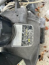
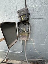
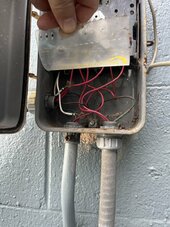
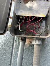
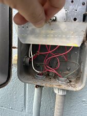
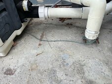
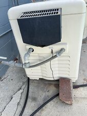
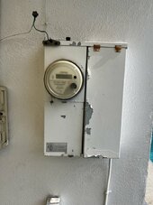
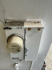
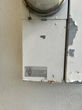
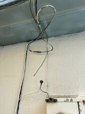
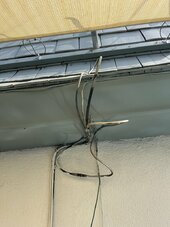
My pool setup has a rusty old intermatic timer device. The mechanical timer parts were removed so that it always stays in the 'on' state. The Jandy variable speed pump has a wifi device that you program the schedule.

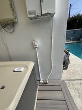
I am wanting to remove that rusty mechanism. I would kill the breaker that goes to the box first, check with my meters/buzzing tools first, take lots of pictures/videos, then remove it from the wall. I think I would be replacing it with just a junction box (or removing the guts of the intermatic box, then using wire nuts to convert it to a junction box).

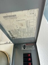
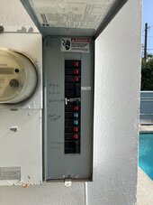
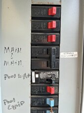
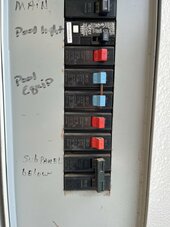
Given that the breakers for this circuit are on the main panel already, is there any reason to put a disconnect or another 240v fuse/breaker in place of the intermatic timer box? I have lots of slack in the wires.

My goal is to put this circuit on solar at some point. Might do a small system (3000 watt cart?) to test my abilities, but concerned about grounding that equipment, so maybe won't start with that circuit.

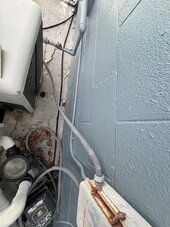
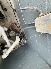
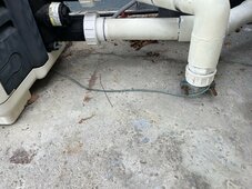
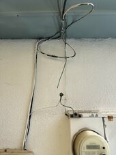
Follow up question: If I did want to break away from the grid for all things pool related, I would kill the breaker, then do what for grounding? If I put an outdoor rated all-in-one for the pool, would I leverage the existing ground wire back to the main panel that is already there (and the equipment is connected to as well as the pipes into the pool), or would I need to create another earth ground and disconnect from the main panel? Asking because I know pools can electrically charge the water, and I want to avoid death.

Open to suggestions. Not doing anything before first learning a lot.
 
Jandy 2 HP variable speed pump. Uses 240v and 15amp circuit. But if the breaker is already in the panel, even if someone plays with the equipment (somehow gets it to turn on outside of the time it is scheduled to run), wouldn't the breaker at the panel do the job? I think the answer is yes; I do have a 30 amp 'air conditioning' sub panel thing I will look at tonight and see - think it would directly replace (same size or so) that intermatic box I have now.
 
A picture inside your old rusty box is worth a thousand words - post it pls.

Assuming it is a standard intermatic timer box and the timer is defunct

turn off the breaker - is it a single or double breaker?

verify power is off at the intermatic box
take a picture - there should be a white wire, a black wire, and possibly a red wire and a green wire.

Where you go from here depends on what you have in your breaker box - post a picture of that as well zoomed in on the pool pump breaker

If your home is older and the breaker for the pump isn't GFCI you have a couple of options
  • Change it to GFCI and wire across the intermatic timer
  • Change the intermatic box to a water tight box and add a GFCI passthrough - no outlet allowed
    • If it is a single pole breaker there are 120v feedthrough at the local hardware store
    • If it is a double pole breaker there are 240v feedthrough at online or at pool stores

The choice of changing the breaker or adding a GFCI is yours if it isn't there - but changing the breaker requires working in the main panel and changing the timer to a feedthrough is working on the circuit with power off.

I would go with the second option from the questions you are asking here and other threads.

GFCI is to protect you and anyone else in the pool in case the pump faults. This way if someone is in the pool and grabs the ladder to get out they don't get zapped.

And if the GFCI already exists then you just turn off power, wire across the switch and turn it back on.
 
Honestly I don't have a pool cover yet. That seems to be the best way to reduce thermal loss at night.

yes it is standard. And old.
Double breaker - 240, 15 amp breaker for each wire (learned today that this means it is just 15 amp circuit).

Old wiring - think two blacks come in plus two others - maybe a green and a white. Will kill breaker, test loads, then take photos - I don't like being around that box. Got zapped as a kid with wet feet trying to turn the pool heater on for my dad. Metal box, old rust, wet fingers - what was I thinking. I was like 7 years old.

Is code to have GFCI to pool equipment these days? If I added it at this 'subpanel' by the pool, and did it right, is there enough wires present to do that without running a wire back to the main panel?

The main panel, frankly, scares me. It has no main disconnect that I'm aware of. Think of it like this: There is a left side, and a right side. The right side from top to bottom has 10 or so breakers in it. On the left side, the panel is split into two. The top has the meter in it. I presume the lines from the roof run down to this section. Below that is another box with an access door that is screwed tight with all kinds of warnings. I assume it just has bundles of wires in it or else the big ones that go between the meter and the breaker panel on the right. The service disconnects are on the right, just two of the 10 breakers joined together with a nail labeled 'service disconnect'.

I will take photos and send later.

I have not ever taken the cover off the breaker panel cover on this panel. It is old and rusty. I confess I am a bit scared, even if I kill the main service disconnect, as I feel like there is lots of power still in that box. Wish it was like others where two big wires connect at top with a massive switch. Then at least I know everything below it is not energized.
 
You can't take the left side cover off without having the local PoCo out to put the seal wire back on it.

With 4 wires you have 2 hots, a neutral, and a ground most likely - will take a picture to verify. Each of the blacks goes to a leg of the breaker, the white is neutral and the green is ground.

You will need a 240v GFCI pass-through and to replace the box with a standard water proof box.

This is the sort of pass-through GFCI to use - you can probably get it at a pool supply/installer or an electrical supply. The big box stores seldom carry it since they don't sell enough of them.

Instructions will be inside the box but -
black wires to the side screws marked line
wires to the pool pump to the side screws marked load
neutral wires to the neutral screws
ground wire all tied together and connected to the ground screw.

And yes - GFCI on anything with water in it is code for safety - if it didn't have it before and you modify it you need to update to code and safety standards.

The main thing is to turn off the breaker and make sure nobody comes behind you to turn it back on - tape across it saying something to that effect. Then verify everything in the intermatic box has NO power before touching any wire.
 
Did you just buy a new house and have a list of projects a mile long to do?

Just curiosity since you are all over the place with new questions - a good thing to ask and understand before doing anything.
 
Pool grounding is critical to be done correctly...
Especially with pool liners and above ground pools...
Nothing like being soaked in chlorinated water and stepping out of an ungrounded pool with a failing motor to liven up the day...

GFCI is critical...
Beware low cost gfci... there are TWO levels of gfci... equipment (low cost) and personell... you want TRUE personell gfci breakers, preferably pool rated...
 
Here are the photos requested. Open to discussion.

IMG_9970.jpeg
 

Attachments

  • IMG_9969.jpeg
    IMG_9969.jpeg
    231.1 KB · Views: 4
  • IMG_9971.jpeg
    IMG_9971.jpeg
    245.8 KB · Views: 4
  • IMG_9972.jpeg
    IMG_9972.jpeg
    242.6 KB · Views: 5
  • IMG_9973.jpeg
    IMG_9973.jpeg
    255.7 KB · Views: 5
  • IMG_9974.jpeg
    IMG_9974.jpeg
    202.5 KB · Views: 5
  • IMG_9975.jpeg
    IMG_9975.jpeg
    187 KB · Views: 5
  • IMG_9976.jpeg
    IMG_9976.jpeg
    157.7 KB · Views: 5
  • IMG_9977.jpeg
    IMG_9977.jpeg
    417.9 KB · Views: 5
  • IMG_9978.jpeg
    IMG_9978.jpeg
    410.4 KB · Views: 5
  • IMG_9981.jpeg
    IMG_9981.jpeg
    174.4 KB · Views: 4
  • IMG_9982.jpeg
    IMG_9982.jpeg
    213.5 KB · Views: 4
  • IMG_9983.jpeg
    IMG_9983.jpeg
    189.6 KB · Views: 4
  • IMG_9984.jpeg
    IMG_9984.jpeg
    261.8 KB · Views: 4
  • IMG_9985.jpeg
    IMG_9985.jpeg
    207.8 KB · Views: 4
More photos
 

Attachments

  • IMG_9983.jpeg
    IMG_9983.jpeg
    189.6 KB · Views: 6
  • IMG_9984.jpeg
    IMG_9984.jpeg
    261.8 KB · Views: 5
  • IMG_9985.jpeg
    IMG_9985.jpeg
    207.8 KB · Views: 5
  • IMG_9986.jpeg
    IMG_9986.jpeg
    121.7 KB · Views: 5
  • IMG_9987.jpeg
    IMG_9987.jpeg
    175.4 KB · Views: 5
  • IMG_9988.jpeg
    IMG_9988.jpeg
    142.5 KB · Views: 5
  • IMG_9989.jpeg
    IMG_9989.jpeg
    124.7 KB · Views: 5
  • IMG_9990.jpeg
    IMG_9990.jpeg
    162.6 KB · Views: 4
  • IMG_9991.jpeg
    IMG_9991.jpeg
    180.5 KB · Views: 4
  • IMG_9992.jpeg
    IMG_9992.jpeg
    180 KB · Views: 5
  • IMG_9993.jpeg
    IMG_9993.jpeg
    206 KB · Views: 6
It appears that you have 2 hots and a ground with no neutral in that box. The two white wires coming from the timer mechanism aren't connected.

It also appears that at some point in the past the lights breaker was replaced with a GFCI model which is good.

The bottom right conduit is the motor, the left side is the control to the heater and the input from the breaker panel is bottom left.

Local code may vary so you should probably see which version of the NEC you are under and if there are any local rules added.

Can you see where the conduit from the bottom left side goes to? It appears to be attached to the wall.

Off the top of my head from what I can see...

In either case - replace the intermatic box with a water tight box

Two ways to do it I suppose -
Simplest -

Replace the breaker with a 2 pole GFCI breaker and you are done


The other way is to get a GFCI device like I listed above and wire things off it...
Now, I can't find the instructions for that online so when you get it if it calls for a neutral wire you will have to buy all 4 wires, lube, and repull them through the conduit.

The wires from the bottom left go into the LINE terminals.
The input wires from your controller go to the LOAD terminals.

The output wires from your control go to the furnace and pump motor wires.

When replacing the box with a water tight one you need to clean up the exposed copper wires wth garnet sandpaper so they are shiny again. Put some no-ox-id or similar on all exposed wires and wire nut the different groups together. Make sure when you buy wirenuts to read the back and get ones for the wirecount you need. I suspect red and/or yellow will do what you want. They will say how many #14 wires you can do in each.
 
More photos
That is an old panel.
Itt or murray?
Likely uses siemens or eaton breakers.
Make SURE YOU GET THE CORRECT breaker replacement for the panel.
Hate to fail an inspection because the wrong replacement is used...

Edit:
Ahh, i see it is cutler hammer, that is eaton BR series breakers.
Easy!
 
Last edited:
Sounds like I could avoid running new wires by getting a GFCI breaker that is made for 240 volts, 15 A per wire, for Eaton br series breakers. Am I right?
 
By the way, there doesn’t appear to be a way to use an interlock device on this panel correct?
Sure, an interlock locking out the main service disconnect in the center should be fine.
Generator Interlock Kit Compatible with Square D Homeline Meter Main 150 or 200 amp Breaker.Professional and Interlock Kit.Electrical Interlocking Kit(SD200SA) https://a.co/d/04VYlOgP
 
While on the subject of pools… We have a pool man that comes to the house once a week year-round. He checks the chemicals, runs the pump for 15 minutes, scrubs the walls, and fishes debris off the surface.

Today he told me that, we should be recirculating the water through the pool more than we are. My discussion with him today was about how to lower power usage. We are doing it for four hours a day in the morning. He recommended doing two more hours at night. Our water has no mold or algae , and we have very few leaves or debris that lands in the pump filter. We also have a large filter system with a four stage filtration system that I guess they remove and clean every six months and put back together.

Today he said our pools is spectacular and is in great shape. I’m not sure why when I approached him about running the pump less he recommended we run it more if it’s in such great shape. Is there any evidence or proof at the water must circulate more?

As I am trying to reduce costs, I’m looking at , other pump options. I’m thinking something that is 12 V or at the very most 110 V that can tie into the existing filter or something like that. That way I can just run an inverter to my 12 V battery and circulate water for six hours a day if that is really necessary. This picture shows the RPMs and wattage of my existing 240 V 15 amp system. I don’t want to buy a massive inverter to run this. Looking for a short win here. The pool is heating with a DIY set up. I built already so we don’t consume any gas on the pool heater at this time.
 

Attachments

  • IMG_0001.png
    IMG_0001.png
    126.6 KB · Views: 1
While on the subject of pools… We have a pool man that comes to the house once a week year-round. He checks the chemicals, runs the pump for 15 minutes, scrubs the walls, and fishes debris off the surface.

Today he told me that, we should be recirculating the water through the pool more than we are. My discussion with him today was about how to lower power usage. We are doing it for four hours a day in the morning. He recommended doing two more hours at night. Our water has no mold or algae , and we have very few leaves or debris that lands in the pump filter. We also have a large filter system with a four stage filtration system that I guess they remove and clean every six months and put back together.

Today he said our pools is spectacular and is in great shape. I’m not sure why when I approached him about running the pump less he recommended we run it more if it’s in such great shape. Is there any evidence or proof at the water must circulate more?

As I am trying to reduce costs, I’m looking at , other pump options. I’m thinking something that is 12 V or at the very most 110 V that can tie into the existing filter or something like that. That way I can just run an inverter to my 12 V battery and circulate water for six hours a day if that is really necessary. This picture shows the RPMs and wattage of my existing 240 V 15 amp system. I don’t want to buy a massive inverter to run this. Looking for a short win here. The pool is heating with a DIY set up. I built already so we don’t consume any gas on the pool heater at this time.


It can help to run the pump more if there is buildup on the walls that he is having to scrub off, meaning less buildup.

Back when we had a pool there were two pumps, one for high speed and one for low speed. The low speed ran 24x7x365 and the high speed one ran only about 6 hours a day. This was down in Texas and the heater only ran long enough in winter to keep the temp above freezing.

You have a variable speed pump, can it be set to run low for a period and higher for a period?

I wasn't the one taking care of the pool, dad always did that himself - so I have no idea of the science behind pool pumps and how long to run.
 

diy solar

diy solar
Back
Top