diy solar

diy solar

Double check my wiring diagram for 12v 300Ah LiFePO4

ironladd

New Member
Joined
Dec 23, 2019
Messages
30
Take a look below. I believe this is correct to get the desired results of a 12v 300Ah LiFePO4 battery pack.
Screen Shot 2019-12-30 at 10.33.45 AM.png

And, in the drawing, that can all be done using bus bars, right?

Thanks

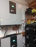
(Install space necessitates the batteries to be configured like this, all in a single row, thus the odd layout)
{Deleted second pic to avoid too many comments on a diagram I know is wrong :)}
 

Attachments

  • Screen Shot 2019-12-30 at 8.43.40 AM.png
    Screen Shot 2019-12-30 at 8.43.40 AM.png
    51.7 KB · Views: 42
Last edited:
The first one look okay. The second one appears flawed.....like some shorted cells.

The second one, are you trying to do 3 series strings in parallel with each other? I think most people would agree that paralleling the cells first is best, like your first drawing.
 
  • Like
Reactions: JAC
The first one look okay. The second one appears flawed.....like some shorted cells.

The second one, are you trying to do 3 series strings in parallel with each other? I think most people would agree that paralleling the cells first is best, like your first drawing.
I'm in complete agreement with you. I did that second one as my first drawing and kept thinking something looked wrong. Started over from scratch and came up with the first diagram.
 
I see 3.2 in 3P = 3.2V and 300ah then 3.2V in 4S = 12.8V
No idea what is happening in the second row, but don't do it.

Remember to just keep it simple. Make one battery set to the voltage you want in series. Then copy that one to make more AH in parallel. It works the opposite also, make a P set, then series it up to the V you want.
Deleted second pic and I think I did what you suggested in first pic. Keep it simple. 1st set is P at 3.2v and 300Ah, then repeat 3 more times in Series to get to 12.8v and 300Ah. Correct?
 
Working it the other way, is this digram correct as well?Screen Shot 2019-12-30 at 12.59.16 PM.png
Each set is 12.8v @ 100Ah, wiring in Parallel to make 12.8v @ 300Ah
(Breaking apart the sets helps, even though they'll be tight during install and all connected using copper bus bars.)
 

Attachments

  • Screen Shot 2019-12-30 at 12.55.34 PM.png
    Screen Shot 2019-12-30 at 12.55.34 PM.png
    19 KB · Views: 2
Working it the other way, is this digram correct as well?View attachment 4194
Each set is 12.8v @ 100Ah, wiring in Parallel to make 12.8v @ 300Ah
(Breaking apart the sets helps, even though they'll be tight during install and all connected using copper bus bars.)
THis is a 4S3P setup. Same V and AH.
The first one is 3P4S, Same V and AH though.

Ummm wait a second, you got two lines connecting between each set.

Here, look a real 2S4P setup.

IMG_20191221_221227675.jpg
 

Attachments

  • IMG_20191224_233621861.jpg
    IMG_20191224_233621861.jpg
    87.3 KB · Views: 14
Last edited:
Working it the other way, is this digram correct as well?View attachment 4194
Each set is 12.8v @ 100Ah, wiring in Parallel to make 12.8v @ 300Ah
(Breaking apart the sets helps, even though they'll be tight during install and all connected using copper bus bars.)

Make the middle one the same as the end ones. You made something kind of weird. I'm not sure what it would end up being.

+ to + to +
- to - to -
 
Last edited:
But you should do as in very first picture 3p4s that means you will only have 4 batteries to balance not 12
Makes sense. An no break is required. I can run all 12 batteries side by side with bus bars.
 
Some folks advise wiring it like this to help ensure you are drawing down all 3 sets equally. (This more or less equalizes the wire resistance to each set of 4)
1577743090534.png

However, If I was building it up out of individual cells, I would do your first diagram:
1577743227965.png
This allows you to use a single balancer system.
 
Some folks advise wiring it like this to help ensure you are drawing down all 3 sets equally. (This more or less equalizes the wire resistance to each set of 4)
View attachment 4200

However, If I was building it up out of individual cells, I would do your first diagram:
View attachment 4201
This allows you to use a single balancer system.
This will work also. :) How much wire resistance is proportional to the total length. The shortest is best.

They are all going to "draw down" equally no matter where you connect the entire setup to the inverter, unless one battery is 40 feet away and one is right next to the inverter, then it might get weird.

I have wondered how much difference it really makes as well. The only reason I give the recomendation credence is the high amperage. .01 ohm resistance would equate to a 3 volt difference at a 300 amp (1C) discharge rate. That is a huge swing. Even .001 ohm equates to .3 volts and that is still pretty big. Most of us don't drive our systems at 1C, but 100 amps (.33C) is probably not uncommon and 1 volt difference is still pretty big.

What I don't know is how different the resistance really is. At the short lengths we are talking about, my guess is the resistance at the connectors will be the dominant factor. Can a couple good connections and links add up to .1 or .01 ohms? (If you aren't doing a good job on the connections, you are likely to have a lot of problems and this possible voltage difference at the batteries may be the least of your worries)

Charging is usually not as big of a deal, most of us don't charge even as high as .25C and as the batteries charge, the current will get even lower, consequently the voltage difference between one battery and the next would start low and drift down as they charge.

This all brings up another question I have had: Why don't the larger charge controllers have a voltage sense lead to put on the battery? (The good quality external voltage regulators for alternators do)
 
Back
Top