diy solar

diy solar

Double Stack Solar Deployable panels...

0truck0

New Member
Joined
May 29, 2023
Messages
216
Location
sillyville
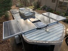
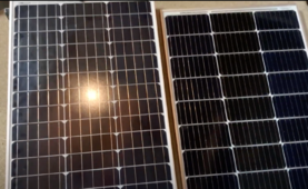
I am building a sliding solar panel with these 100w .
The plan is that the top one slides out when parked, when needed, and doubles the solar capture. A 100 w over another 100w, and on both sides of trailer.
I have substantial wires inside, so the question is NOT about wires or what wires do, please I do not need info on wires...

Anyone see any issues if I run the two panels parallel down the same wire? The controller will be fine. **edit, I ran new cables. new controller, so trailer has 3 complete sets of solar systems and two sets of batteries.**
The shaded panel and the top (always in sun) panel wired together parallel (go into the same positive wire / going to controller and to same negative wire).
Two 100w panels in series (the two top panels always in sun) and two 100w panels (lower panels) in series also. So, this is a 200 w 24v (36v) (each panels says 5.8 amps) times two. At full sun, fully deployed, this is 400 watts, 24v, when not deployed is only 200 watts 24v, and the other 200 watts 0v is in the shade.
And, if you dont understand please hold off comments as dont want forum filled with unrelated comments, just DM me first.

The question is:
Is there any issue having a dark panel connected to same wires as sunlight panel? Will the dark panels suck wattage?
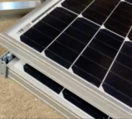
bleStk.png
Panels will be stacked, and the lower one will be completely in the dark when closed, and fully in sun when open.
dblepanel.png
 
Last edited:
I don’t see any issues. You could put a blocking diode on each string.

I’ve only done the short term of what you describe, but not all day long.
 
I thought about diodes, but don't they reduce voltage a little?

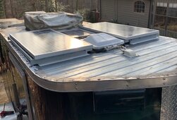
Panels mounted: only the lower/inner panels are connected so far.
I had to take the original panels that were in the center spot off because these paired with the outer ones perfectly for a drawer slide set-up, so the original wires are just swapped over to the new center panels.
The outer panels are a few inches longer than the inner ones so attach to the drawer slide. Slides are cheapo ones somebody gave me, but do not have ball bearings to rust or get dirty.

deployd.jpg

I did a vid too. One long aluminum angle iron going all the way across on back which helps hold the deployed panel.
You see the white angle iron aluminum pieces on the very front of panels, these could not go across bc of the vent, but I will make a physical connection - the concern being the outer panels leveraging the VHB tape off near the vent on a hot day. **edit - I screwed a bar just behind the vent to connect the panels, much more stable now*
Center panels are wired to the gland in front. The outer panels probably will enter next to it closer to the side.

There is another pair of 100w panels on the rear. The story is I have a 200 amp hr batt at front for fridge that is fed from front panels, and at the rear another 200 amp hr battery fed from the rear panels that powers everything else. Batts can be connected w a switch - never needed to. Can also be connected via switch to alternator, but never needed that yet.
The additional panels (now the bottom center front ones) will feed either battery that needs it if/when it needs it via the A-B switch.
**edit, the deployable ones were easier to put on a switch so they are the electable ones. no re-wiring of existing panels needed, lol**

Total 600w, which is a lot for this small trailer.

The center ones **deployable now** will be on an A-B switch so I can send power to either battery bank or turn off. The switch also has an A-B setting to send to both, this will also connect the two batts together to make one big batt bank of 400, not ideal but possible...
Maybe
I still might connected all 4 front panels parallel and in series for 24 volts down the same 2 cables that goes thru roof, undecided. **nope**

Another question, and I think I know but too tired....
If I put a switch on the positive of A and B batteries (two separate battery/solar/controller systems) will the shunt still calculate the battery useage correctly? The shunt is on the negative. Shunt set up for their dedicated panels, but now with the extra panels if I feed more into them, with another charge controller too, the shunt should be fine? **shunts are effectively the neg battery post now so no matter what is done, shunt still works.**

Closed up:
innie.jpg

Tiny cnter panel is for a dedicated exit sign battery that is for the brake emergency stopping. 25 yrs old and 15-20 watts. I had it so using it for no reason for the brakes when I coulda used either big battery...
 
Last edited:
If I put a switch on the positive of A and B batteries (two separate battery/solar/controller systems) will the shunt still calculate the battery useage correctly? The shunt is on the negative. Shunt set up for their dedicated panels, but now with the extra panels if I feed more into them, with another charge controller too, the shunt should be fine?
Yes this is fine.

Shunt will measure what it’s hooked to and I think you want after both batteries combined on the negative side.
I thought about diodes, but don't they reduce voltage a little?
This is a good video
They do use a couple of watts each. Most will believe blocking diodes are not good. Your situation is a little different. Since half the panels are shaded and parallel to another all the time, may be worth it in this case.
 
The panel has the diode so the other panel or the battery cannot feed the shaded panel power. That answers that question.
That's a good vid, I did not know about the bypass function.

I Will's video... Define "shaded". Does he mean completely covered/blacked out or just shaded where the sun light is less, but still there?
IF the corner of my roof vent shades one cell, then will that bypass the entire section, or just reduce voltage slightly?

So, given this new info, I could combine all 4 panels in series at 48 volts into the mppt and even when the lower ones are under the upper panels the blocking diodes in the panels will bypass the lower covered panels and the upper ones will function as what, 24 volt then?

**edit. wow, I tried it. I covered one cell and it killed the whole panel. Covered a third of one cell and it did a little better.
 
Last edited:
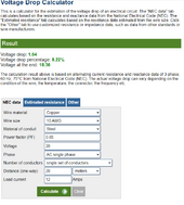
I think your original plan with 2S2P with the parallel panel being a slideout is valid PROVIDED voltage loss is not an issue. You do have about 8%, I'd plug your own numbers in here to be sure. IMO, 8% loss is acceptable, BUT 18.36 Volts MIGHT be too low. A shorter run, thicker wires, higher voltage, less amps could be good.


1709566700150.png
As a rule, I like putting as many panels in parallel as possible for an RV so that shading a panel won't ruin a string.

For shading, this is the results I have of a string set up 3S and a separate string set up 2P.


For the Blocking diodes, you can always add those later provided your combiner box has the room for this. The amount of extra power a blocking diode gives you may equate to a few extra minutes of charging to reach 100% every say, if that.
 
Now I am rethinking everything givin these shade results.

I wonder if I should run the right panels into one controller and the left into another controller.
Then if that, should I run the parallel or in series. If in series then the lower one on each side would be hidden most of the time which means that panel gets bypassed,
but how would the controller act if in series and power is cut from 24 to 12 volts? It has been a while since I programmed the controller.
IMO, two controllers would be better, I’d also recommend making the run long enough so that the combiner is easily accessible and panels can be rewired so its best.

Because of voltage loss, the two exposed panels in series to one controller, and two slide out panels in series to another controller. With parking the front to the south, whatever is covered onthe roof in the back would not cast shadows.

If you put the left panels in series and then the right panels in series, whenever the panels were not extended, that would kill your production. Parallel it would not.
 
Thanks, so sounds like I either need to run 4 panels parallel with 4 controllers, or keep it as is with the top ones in series into a controller and same for the bottom ones.

I debating about the rear ones now.
I want to do same in the rear, but I need to find these exact drawer slides, hard to do.
or I kinda want to remove the vent fan at the back, lay down one more panel there (for 3 on the rear), run 3 parallel due to shade issues discussed. I would rather do series, but again, shade issues. Then I put the fantastic vent fan on the rear door.
I have too much time on my hands this week, but I did add a soft start to the roof ac, so I guess I will keep the roof ac for a while.
 
The deployable panels were added and the existing ones left alone - as this way I did not have to un-do any existing panel wiring in a tight space.
The top panel is the deployable and it is selected to power the front battery because the front batteries panels are under the deployable ones. So, when deployed the front battery has its own dedicated solar panel and then I can decide where to use the deployable panel - front or rear battery or connect both batteries together which will connect all the solar charging together.
The rear batt is on a 14 foot set of cables bc it is 12 feet back. Too much tongue weight already so I put that battery at the rear for balance. When the two are connected the front batt gets drained faster than the rear bc of the long cable run to the rear. I really have no reason to connect them I can think of but since the switch can do it I did wire it to do it. The switch is mostly to send solar to either battery in need.

Had I done this from scratch I would have put the rear controller at the rear, but as is it was already set up at the front and the shunt cut in at the front, so I just ran long wires. Panels are at the rear, cables go to the front where the controller is, then go back to the back where the batt is. from panel to batt is prob close to 30 feet, but it works just fine. I used heavy g wire. I do not run significant big loads off the rear batt, so this helps.
 
Back
Top