diy solar

diy solar

Drafted my design- aiming a 4.5KW grid tie system

Solarisium

New Member
Joined
Jan 7, 2023
Messages
107
Location
SoCal LA
Hi Solar folks!

I just started my journey! Yep it is a journey for a true DIYer. Here is design (still a draft):

I have a clear idea of what I am going to install: a 4.5 KW SMA grid tie system. no power optimizer, no micro inverter, no battery or storage devices. Plain and simple.
I will probably use new or unused panels to generate 4.5kw. will connect them in parallel/series to get to 240 volts. Will run it to a 5.0 kw SMA string inverter and from there to a rapid shutdown switch and to the fuse panel.
Right now I am searching for the right panel and inverter to order. Might use unused blemished 10x450w OR new 16x250 w given the space on my roof.

regarding the NEM application: I started the online application on SCE. SCE has all the forms you need to fill out and an online application tool. It’s a great resource for DIYers to find out what forms and information are needed to get their NEM approved. I have not submitted my application just yet as I am still finalizing the design and need to find a whole seller online to order the parts.
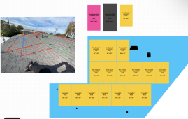


74DFA827-75D7-44D2-AFF5-15AB3D74B587.png
In order to draft my design I took a photo of my south facing roof. Then edited the photo and drew lines to designate species for solar panels. Went to the roof again and measured everything. Used Freeform app on my iPad and drew this to scale. finally I used a spreadsheet to find out how many of each panel type I need.
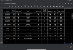
44F7D642-6DCA-4BEE-8A29-877FD5283658.png
Then tried to fit them on my design to find out if sufficient number of panels can fit to generate ~4.5kw. The small black shapes are the plumbing vents or attic vents since they are the obstacles, needed to be identified in the design.


My timeline is April first. On April 13 the NEM 3.0 will be effective, which means longer payoff times. There are two pieces of the work that I haven’t completed my research. The local township permit and the racking system.
I appreciate if anyone has any advice for me at this point.

p.s. I am hoping my post is in the right place. If not, will move it.
 
I like iron ridge and local rexelusa can deliver the racking material to your house to avoid shipping. Ironridge designer will also create a package with calculations to submit for permitting purposes.
 
I like iron ridge and local rexelusa can deliver the racking material to your house to avoid shipping. Ironridge designer will also create a package with calculations to submit for permitting purposes.
Thank you!
I found a local store carrying the racking supplies and will take a look this weekend. This was great, as I needed some support there.


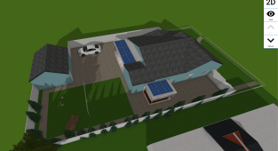
Now need some help with the design as my design is not finalized yet. I used an app to design my home and find the best places to install the panels. I don't want to put them on the roof for the following reasons:
The current roof is a bit old (15 years ish). Don't have time to re-roof, and don't want the risk of having leaks. plus I need to finish this project before NEM 3.0 which goes into effect on Apr 23.


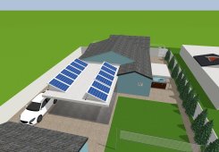
So I decided that I will install panels on the flat roof area that is available to me. See the picture:
Few things: my current consumption is 200 to 400KW per month. A small 3KW system is sufficient to cover this consumption. So I decided that I will install 9 or 10 x 455w panels so that after deducting all inefficiencies I will still get close to 4500 KW annually in the worst case conditions (as shown in the picture: winter sun hours, long shadows, no tilt panels and some shades here and there).
Screenshot 2023-01-12 at 10.32.53 PM.png
Once I install the system within the timeline and under NEM 2.0 under the nameplate of 10x455w=4550w and secured my spot in NEM 2.0, then I will have enough time to expand the covered patio and move all the panels to the new area, tilt them for higher efficiency and add two additional panels without breaching the NEM 2.0 contract so the system size will be 5400w. I will need to start with a 6.0KW inverter from the get go and design everything with 5.4KW in mind (you are allowed to add up to 1000w to your system and stay in the same contract with your utility company, in my case SoCal Edison):
IMG_0113.jpeg


The reason for the hurry is that under NEM 2.0 my utility company credit s me for the power I generate per the retail rate while under NEM 3.0 the credit given to my for extra energy will be 2 to 4 cents per KW. Under NEMn2.0 my payoff time will be 5 to 6 years, while under NEM 3.0 it will be much longer than that (10 years? need to calculate it.)


I appreciate if someone review this and give me thoughts. What am I missing? Does this plan make sense?
I plan to install a grid tie system, no power optimizer, no micro inverter, no battery. Plain solar panel-SMA inverter system.
 
Last edited:
Thank you!
I found a local store carrying the racking supplies and will take a look this weekend. This was great, as I needed some support there.


Now need some help with the design as my design is not finalized yet. I used an app to design my home and find the best places to install the panels. I don't want to put them on the roof for the following reasons:
The current roof is a bit old (15 years ish). Don't have time to re-roof, and don't want the risk of having leaks. plus I need to finish this project before NEM 3.0 which goes into effect on Apr 23.


So I decided that I will install panels on the flat roof area that is available to me. See the picture:
Few things: my current consumption is 200 to 400KW per month. A small 3KW system is sufficient to cover this consumption. So I decided that I will install 9 or 10 x 455w panels so that after deducting all inefficiencies I will still get close to 4500 KW annually in the worst case conditions (as shown in the picture: winter sun hours, long shadows, no tilt panels and some shades here and there).
View attachment 129359
Once I install the system within the timeline and under NEM 2.0 under the nameplate of 10x455w=4550w and secured my spot in NEM 2.0, then I will have enough time to expand the covered patio and move all the panels to the new area, tilt them for higher efficiency and add two additional panels without breaching the NEM 2.0 contract so the system size will be 5400w. I will need to start with a 6.0KW inverter from the get go and design everything with 5.4KW in mind (you are allowed to add up to 1000w to your system and stay in the same contract with your utility company, in my case SoCal Edison):
View attachment 129367


The reason for the hurry is that under NEM 2.0 my utility company credit s me for the power I generate per the retail rate while under NEM 3.0 the credit given to my for extra energy will be 2 to 4 cents per KW. Under NEMn2.0 my payoff time will be 5 to 6 years, while under NEM 3.0 it will be much longer than that (10 years? need to calculate it.)


I appreciate if someone review this and give me thoughts. What am I missing? Does this plan make sense?
I plan to install a grid tie system, no power optimizer, no micro inverter, no battery. Plain solar panel-SMA inverter system.
Will you satisfy rapid shutdown requirements from your local jurisdiction?
 
Will you satisfy rapid shutdown requirements from your local jurisdiction?
I will install one right before the breaker panel.

I’ve seen one in one a wholesale site, but never got too deep into it.

Do you have any recommendations?

Thanks anyways.
 
I will install one right before the breaker panel.

I’ve seen one in one a wholesale site, but never got too deep into it.

Do you have any recommendations?

Thanks anyways.
Rapid shutdown is different from ac disconnect since you are using string inverter. I don’t remember the exact numbers and code but you can search rapid shutdown on this forum.
 
Rapid shutdown is different from ac disconnect since you are using string inverter. I don’t remember the exact numbers and code but you can search rapid shutdown on this forum.
I did some research.
It appears that solar edge power optimizers actually do provide rapid shutdown feature.

But sma sunny boy needs another device installed on module level to satisfy that code (NEC 2017).

Having seen any video on installing string slats worth rapid shutdown devices for a grid tied sma sunny boy inverter system.
That is what I'm aiming to install.
Appreciate any information on this.
 
Since my last post in Jan, I’ve made some good progress.

My system will be 4.1KW, grid tied, SMA sunny boy inverter with APsmart rapid shutdown devices.

One thing particularly challenging was the array design. I don’t have much south roof space available, so had to go with high power modules to get the most possible out of my space.

Here’s what I’ve purchased:
3.8kw SMA inverter
10 SolarEver 455w panels. 9 will be installed.
APSmart plc rapid shutdown to meet the code
AC disconnect.
Will use rigid metal conduit
No derating main breaker needed.
will need to drive a ground rod since only one current ground rod deives to earth. The other is connected to water pipes. Code might require a second one.

Will use ironridge flashfoot 2 system.

Submitted my permit to the city. Received comments for corrections (2 things: a minimum of 36” setback on each ridge is required one one side, and minimum of 60” on the other side. Had to change my array to meet this code. Made it challenging.
The other comment was to use rigid metal conduit instead of EMT conduit). Made the corrections and sent back. Pending next step, which is usually fees payments.

I also submitted my application to Southern California Edison to get approved while NEM2.0 is still alive! Still pending a response from SCE. hopefully I get approved prior to Apr 14.


Bought solar panels from santansolar. Signaturesolar had the same modules but was out of stuck.
Bought inverter, rapid shutdown devices and disconnect from Ecodirect.
Will buy racking from ironridge once the city approves my permit application for the current aray.

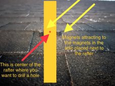
In meanwhile I’ve been researching for the best way to find the rafters to install the racking. I was thinking about sonar devices, or even X ray devices to take a picture and see through the roof! But those are not viable options. finally came with this idea! Using magnets to trace the rafters it worked like a charm!!!

I went inside the attic, glued one magnet on each side of the target rafter, and went back on the roof and used another magnets to find the perimeters of the rafter! Find two points on one rafter, draw a line and then go to the next rafter, or calculator 16” or 24” from the reference point to the left or right.
It works perfectly! You just have to go to the attic and back to the roof at least twice. Also you must use strong magnets made of rare earth elements. See the picture for a visual explanation!
Hope this helps someone out there.
F29A51E2-72EE-43DE-9466-E91A931CE001.jpeg
 
The small black shapes are the plumbing vents or attic vents since they are the obstacles, needed to be identified in the design.
For future reference when you get around to moving panels to the sloped roof, you might want to check your local codes. Mine will allow a panel to cover a plumbing stack vent as long as there is an air gap, and the vent pipe doesn’t need to rise any more than six inches above the roof surface. However, a forced air vent (such as from a bathroom vent or stove hood) cannot be covered. Many codes also will let you vent into the attic, depending on other factors, so you might be able to gain space for another panel or two where you presently have those vents. Good luck.
 
Those vent pipes!

I happen to have almost all vent pipes and attic fan on the south facing roof (4 of them). Made it challenging.

Yes apparently the code allows cutting the vent pipes down to 2 inches!!

Initially I was planning to cut them and install panels over the pipes. They want an issue to the AHJ. The AHJ required 36” and 60” setback from the ridges. That killed most of the space available to me! In my new array design non of the venting pipes will be cut.
 
The AHJ required 36” and 60” setback from the ridges.
I wonder why such a large ridge setback is needed. Did they say? Is it for aesthetics, or for potential firefighter safety, or something else?
 
They mentioned the fire and building safety code:

This was the comment: “Per TMC 85.2.110, specify a minimum ridge setback of 36” on one side of all ridges, and 60” on the other side.”


This is the code:.

“85.2.110 ENERGY SYSTEMS. [ADMINISTRATIVE, CLIMATIC, TOPOGRAPHICAL AND GEOLOGICAL]​

Chapter 12, Energy System, of the California Fire Code shall be amended to read in its entirety as follows:
1205.2.1 Solar photovoltaic (PV) systems for group R-3 buildings. Solar photovoltaic (PV) systems for group R-3 buildings shall comply with sections 1205.2.1.1 thorough 1205.2.1.2, sections 1205.2.1.3, 1207.11.3 through 1207.11.4 and 1207.11.6.
1205.2.1.1 Set Backs for Ridge for Smoke and Heat Ventilation. Panels/modules installed on the roofs of residential buildings shall be located only on one side of any ridge in order to allow for Fire Department smoke and heat ventilation operations. The panel/modules(s) shall be located no less than 3 feet from the ridge.
Exceptions: Where solar panels/modules are placed on both sides of any ridge they shall be spaced a minimum of 5 feet on one side and 3 feet on the other side of the ridge.
 
Why my efficiency is only 50%?
Please help me troubleshoot.


My 4.1 Kw string inverter system generates only 2.1kw. Only 51% efficient.

What could be the reasons?

9x 455 w solar ever mono modules tilted 23 degree south facing. connected in series.no shade.
Apsmart rapid shutdown devices connected to each module.
no MC4 connectors used! Modules connected to the APsmart devices and to the next module.
Distance from the last module to the inverter 15 ft using 10G wire.
Distance from inverter to the main panel 10 ft using 10G wire.

Inverter: SMA sunny boy 3.8 US 41.

Weather: typical SoCal fully sunny day.
Module temp: 100F (37C).

Checked it again: 2094w, 295V, 7.36A

A bit disappointing!
Was expecting at least 75% efficiency.
 
Last edited:
I will probably use new or unused panels to generate 4.5kw. will connect them in parallel/series to get to 240 volts. Will run it to a 5.0 kw SMA string inverter
My only suggestion is that since you have plenty of room to add more panels that you plan for that. Having 4.5 kW of panels feeding a 5 kW inverter is a waste of inverter capacity but it does give you capacity to expand in the future. The panels will lose capacity over time and rarely output their capacity except in unusual circumstances. You could add another 1.5 kW of panels without compromising production of that inverter. The sweet spot of DC to AC ratios is around 1.2 to 1.
 
Last edited:
Of the 24 flashings I attached to the roof, none missed the rafter!

Also went into attic after a heavy rain we had, it was dry! No sign of leak was observed!

Fantastic, you learn something new everyday
 
Last edited:
My only suggestion is that since you have plenty of room to add more panels that you plan for that. Having 4.5 kW of panels feeding a 5 kW inverter is a waste of inverter capacity but it does give you capacity to expand in the future. The panels will lose capacity over time and rarely output their capacity except in unusual circumstances. You could add another 1.5 kW of panels without compromising production of that inverter. The sweet spot of DC to AC ratios is around 1.2 to 1.
I plan to add one more panel in the near future. I locked myself in NEM 2.0 so any addition over 1kw will land me in NEM3.0 which I want to avoid.

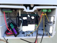
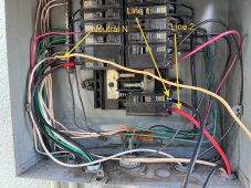
Later today I realized that my inverter was outputting 120v AC! After digging deeper I realized my line and neutral connections to the inverter are incorrect. Now I connected line one and 2 , and then connected neutral. Turned on the inverter and it was correctly outputting 240V!

I’ll attach a picture of the connections for those who might be in my situation.
I wasn't able to verify if that was the reason of having 50% efficiency since it was almost night time and the system was barely generating anything.


For some reasons the inverter capped the DC voltage at 290v when I incorrectly connected 120v AC to the inverter. Now that I correctly connected the inverter to the grid with AC output of 240V, I will try it once more at the peak sun hour. Hopefully I am at least at 80% efficiency.

Attaching two pictures showing AC lines and neutral connections from the sunny boy inverter to the main service panel.
IMG_0738.jpegIMG_0740.jpeg
 
Last edited:
In meanwhile I’ve been researching for the best way to find the rafters to install the racking. I was thinking about sonar devices, or even X ray devices to take a picture and see through the roof! But those are not viable options. finally came with this idea! Using magnets to trace the rafters it worked like a charm!!!

I went inside the attic, glued one magnet on each side of the target rafter, and went back on the roof and used another magnets to find the perimeters of the rafter! Find two points on one rafter, draw a line and then go to the next rafter, or calculator 16” or 24” from the reference point to the left or right.
It works perfectly! You just have to go to the attic and back to the roof at least twice. Also you must use strong magnets made of rare earth elements. See the picture for a visual explanation!
Hope this helps someone out there.
View attachment 139365

Sonar is actually pretty viable for many applications. I use it all the time. Not sure if it works through roofing. It is how I find studs behind sheetrock, but didn't work for a wall between adjacent condo units because that has 2 layers sheetrock (probably a small air gap.)

iu


Magnets - that's what I was planning to try for my new house. I intend to lag screw standoffs to rafters.
Glad to hear it works. I've got a tube of rare earth magnets from Harbor Freight. I'm thinking of putting them on a clamp that can grip the rafters.

iu
 
Back
Top