diy solar

diy solar

Dual EG4 6000XP AC Wiring and Disconnects for grid supported PV/Battery system

newtosa

New Member
Joined
Apr 30, 2024
Messages
15
Location
USA
Hi all - I’ve watched all the videos and read lots of the threads (but definitely not all of them). People seem to be comfortable with different levels of planning vs experimentation on these setups for multiple inverters. I’m hoping to cut down on the mistakes (and the costs), so if you have relevant experience I'd really appreciate your feedback.
 
Last edited:
I'm planning the AC wiring for my inverters, at a country house where we have a backup generator and are planning a PV array and battery bank. Like many others, I'm planning to use multiple 6000xp inverters (Luxpower, labeled as EG4) because of the AC grid pass-through functionality. I have a few questions for the group, and if you have relevant experience I'd appreciate your feedback.
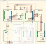
1717128467434.png

Main objectives:
  • The purpose of the PV/battery bank is to reduce reliance on the power company (not to eliminate it). No plans to sell back, given current power company capability/policies and net metering trends in general.
  • For everyday use, the plan is to have the house load powered by PV power when it's producing, battery when PV is not producing, and a combination of PV+grid when load demand is high enough to require the AC pass-through.
  • My family isn't as into this whole scene as I am, so there has to be an "easy button" for them to return to full power-company power if needed (e.g., all the inverters fail, or some similar situation). As a result, I planned a bypass circuit using a manual transfer switch... throwing that switch to grid would bypass the inverters completely.
  • The generator is there as a backup for short-duration outages at the power company (local weather, grid problems, etc.). My preference is to leave its wiring alone (i.e., it will continue to serve as a "backup grid" in this setup).
  • All the other typical goals: no grid backfeed, etc.

Details and Questions for the group:
  • The attached wiring diagram has the current hardware and wiring (shaded in white) and the planned additions/changes (shaded in yellow).
    • Currently (in white), the power company mains goes from the meter to the ATS. The ATS feeds either grid or genset power to the load side in a 200A main-breaker service panel. That main panel serves the large 240v appliances and a shop directly, and the house's 120v circuits in an interior service panel inside the house.
    • The new wiring (in yellow) will instead feed the ATS output to a distribution panel (200A bus rated), which feeds all the inverters through 50A circuit breakers (one per inverter). From the inverters, the 50A circuits are then combined and fed to the MTS bypass switch.
    • The distribution panel's feed-through lugs pass power to the MTS bypass switch... normal operation for that MTS is to leave this grid circuit open and keep the inverter circuit closed (I know the diagram shows otherwise, but I got tired of messing with the drawing tool).
  • Does this wiring diagram accomplish the main goals?
    • Any concerns?
      • I still need to open up my ATS and confirm it has an outbound circuit breaker... otherwise of course I'll need the Distribution Panel to be a main-breaker panel, vs a main-lugs panel.
      • Also, the grid bypass circuit (at the top of the diagram) isn't switched on its own... I see pros and cons to that. The pro is that the MTS bypass switch is truly an "easy button" (no circuit breaker to check, in a scenario where the inverters all fail and there's no way for grid or genset power to get to the house). The con is that I would have to take the whole house down by opening the ATS outbound circuit breaker in order to work inside the bypass switch/MTS. Should be a "never" kind of scenario, but as soon as you plan for never.... Anything I should be considering here that I'm not?
    • Anything I'm planning that could safely be done with fewer steps or less-expensive hardware?
  • The inverter's AC inputs are spec'ed at 8awg. I hear it will accommodate 6awg. Is that a wise move? In a 2-inverter scenario, I expect each inverter will be running between 3k and 6k watts during the summer peak hours (summer whole-house consumption runs 3kW-5kW in the afternoon, 4kW-10kW from 8pm-11pm, and 2kW-5kW until about 2am). If I see we're running the inverters too close to full duty rating, I'll add a 3rd inverter (which seems to be the appeal of the 6000xp).
  • Generator AC connection: is there any disadvantage to routing this to the inverter's Generator Input vs as it's currently wired (into an ATS with the power company mains, where either source will appear to the inverter as Grid)? Any functionality of the inverters that I'll be sacrificing?
  • Neutral: Is this correct as drawn (bonds and non-bond connections)?
  • Manual transfer switch rating:
    • Obviously there's a huge price delta between 100A and 200A MTSs. I'm planning a 200A switch but would love to find a way to save $500 on a component that's required for peace of mind but isn't essential to the everyday-use scenario.
    • I've had a Sense home energy monitor on the house for about 10 months now (covering the summer, when we often have both AC units and the oven running in addition to 1-2 circuits in the shop, etc.)... that peak load is 14.5kW, mostly to 240v loads (so 60 Amps). If you bump that up a little (since some of that 14.5kW is to 120v loads)... even an adjusted 16kW would only be 67A. I still need to put soft-starts on my non-inverter AC units, so that will come down some.
    • Nutshell: peak load in the summer is between 60A and 67A (and will be lower once I get around to soft-starting the compressors).
    • In a scenario where I choose a 100A MTS instead of a 200A MTS, here are the things I'm thinking about:
      • The 100A MTS doesn't accommodate 2/0awg copper (which is what I have now from the meter into the ATS, and on to the service entry panel).
      • If I were to use 2awg (rated for 130A if THHN) from the Distribution Panel to the Bypass Switch, and then to the SE/Loads Panel... the 200A breaker in my SE Panel may not adequately protect that wire. Would I need to change out the main-breaker in that panel to a 100A or 125A?
      • If I did all that... is there anything else I would need to solve for? Or should I keep this all as currently drawn, use the 2/0 wire, and just get over the cost of a 200A-rated MTS?


Thanks in advance for the feedback and ideas!
--------------------------------------------------------------------------------

Other background if helpful...
  • I've reviewed the threads here:
  • Not pictured (planning these separately and will pull it all together soon):
    • Generator wiring into the ATS (whole-house genset into the ATS has been in place for 2+ years; no plans to change any of that)
    • PV arrays and DC disconnects into the inverters (still thinking/sizing panels & strings into the MPPTs on each inverter)
    • Battery bank (60kWh gets me ~250 days of full-day coverage per year... am waiting for 280Ah vs 100Ah pricing to stabilize a little more, and will plan my battery sizing from there)
    • Stop/RSD circuit
    • etc.
  • Based on my location and the AHJ, there are no inspections required. That said, it's important to me that the system is reliable and safe, and that we follow code with this project.
 
Last edited:
A question for the group... For the way I'm planning to wire this:
  • meter --> ATS --> inverters --> loads panel, in the "normal operation" scenario;
  • meter --> ATS --> MTS (bypassing the inverters) --> loads panel, in the exception scenario...
my understanding is that backfeed is prevented. Do I have that right?

My electrician (who is very thorough and teaches electrician classes at the local county college - but who has zero experience with solar or the newer inverters) asked how the inverter prevents backfeed in a setup like the one I'm planning. While I realize electrons don't just flow one way unless it's at a higher voltage than the alternatives... I imagined some super-sized diode on the Grid input side of the inverter, but when I said it out loud, it sounded weird. How does the inverter actually prevent backfeed ("upstream" of the inverter, in my case, where the "downstream" is controlled by an MTS)?
 
Truly would appreciate people’s feedback on the wiring diagram for this system I’m planning.
 
Last edited:
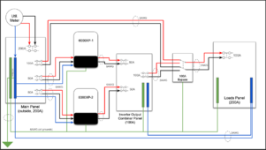
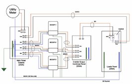
So, I ended up going with a blend of the two schematics. I am designing for two 6000XP inverters but installing one. I prefer the interlock at the panel. You should move your generator to the inverter input and remove/abandon your ATS.

Inverter System Grid Tie Design.jpg
 
So, I ended up going with a blend of the two schematics. I am designing for two 6000XP inverters but installing one. I prefer the interlock at the panel. You should move your generator to the inverter input and remove/abandon your ATS.

View attachment 220655
I’ve thought about that too… planning for two (or three) inverters and starting with one to learn (similar idea for the capacity of the battery bank).

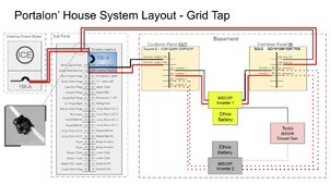
Thanks for posting your drawings. I learn a few things from everyone’s plans.

I see the way you’re bringing your generator in. What’s the advantage to doing it that way? Is your setup non-solar? For my planned setup (with both PV and battery), do you see an advantage to pulling the genset into the inverter rather than treating it as an alternate grid?

One reason I’m leaning towards leaving mine as is - in the event of inverter failure, my genset power can still get to the loads if the power company is down. The down side to my design is that I’m completely reliant on the ATS in all scenarios.
 
Last edited:

diy solar

diy solar
Back
Top