diy solar

diy solar

Dual victron 150/45

Sportzfann

New Member
Joined
May 17, 2020
Messages
93
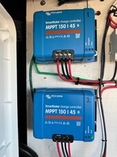
I am looking for some steps to follow to install dual CC.
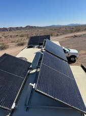
I installed 4x325w panels on my rv roof I have some shading on a couple panels I guess during the summer less shading?
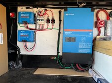
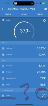
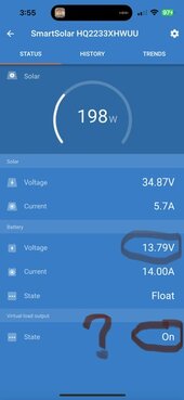
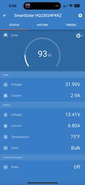
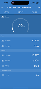
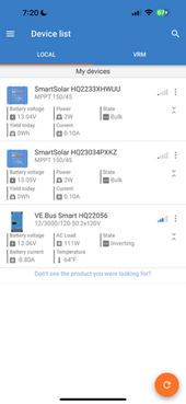
I have 1 150/45 blue smart CC installed and it is maxed out on the amps, the panels are in a 2S2P configuration. (Seems to max out at @600w during full sun)

I figured I should be getting more from this array and spoke to others in this forum and thought I was limited by the controller, so the cheap route was to buy another 150/45 and separate the array to 2 pairs of panels 2 on each controller.

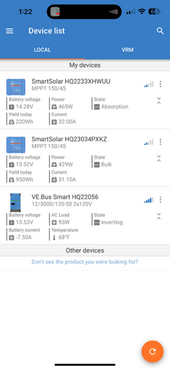
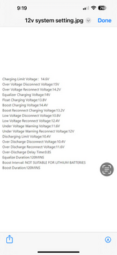
I wanted to ask about the settings so both controllers are at the same setting for bulk Volts and float Volts?
can I make the changes on my phone app so they are both the same settings ?
I don’t have the funds at this time to buy a Cerbo, so I just need to run these as stand alone for now.

Because of some shading is the best configuration to parallel 2 panels to each controller or series to each controller?
Should I have 1 shade panel with one full sun on each CC so they both have a little shade on each pair?

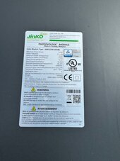
I attached the battery specs from Litime, and the panels I installed.
Thanks, Sportz

2x 200ah Litime batteries
4 jinko 325 panels.
 

Attachments

  • IMG_3633.jpeg
    IMG_3633.jpeg
    100.7 KB · Views: 5
  • IMG_3781.png
    IMG_3781.png
    99.3 KB · Views: 7
The mppt 150/45 maxes out (per the data sheet) at 650w @12v). So yea two makes sense.

Those panels have a Vmp (working voltage) of 33.6 - so you can go either parallel or series.

On RV’s different people say parallel is better - others say series is better… you have the stuff for one set to be parallel- you could hook the other array up in series and see which one produces more power over time. (Track with the total produced amps on the history page).

To answer your question- I would have two panels in full sun on series, and two that tend to get shade in parallel- but that would destroy the parallel-series experiment… 😎. But if that’s not convenient hook them up the best way possible.

You can have them set for exactly the same bulk &float and they will be very closely ran. Just use the phone app to set everything up - works great!

Do you have a Smartshunt or BMV712 - if so setup the Bluetooth VE.Network to pass voltage and current (and temp if you have the temperature sensor). That really helps get everything exactly dialed in - and it compensates for one charger seeing the others voltage.

Just wanted to make sure you are running a new set of wires from the panels to the mppt SCC and also a new set of 6awg wires from the mppt to the battery/bus bar.

Good Luck!
I like the idea of experimenting with the pairs so yea I think I will start with the 1pair series and 1 pair parallel.
I have #8 and#10 to bussbar then #4 to the breaker and then the battery bank.
 
The mppt 150/45 maxes out (per the data sheet) at 650w @12v). So yea two makes sense.

Those panels have a Vmp (working voltage) of 33.6 - so you can go either parallel or series.

On RV’s different people say parallel is better - others say series is better… you have the stuff for one set to be parallel- you could hook the other array up in series and see which one produces more power over time. (Track with the total produced amps on the history page).

To answer your question- I would have two panels in full sun on series, and two that tend to get shade in parallel- but that would destroy the parallel-series experiment… 😎. But if that’s not convenient hook them up the best way possible.

You can have them set for exactly the same bulk &float and they will be very closely ran. Just use the phone app to set everything up - works great!

Do you have a Smartshunt or BMV712 - if so setup the Bluetooth VE.Network to pass voltage and current (and temp if you have the temperature sensor). That really helps get everything exactly dialed in - and it compensates for one charger seeing the others voltage.

Just wanted to make sure you are running a new set of wires from the panels to the mppt SCC and also a new set of 6awg wires from the mppt to the battery/bus bar.

Good Luck!
Rocket, I have the 2 in parallel on each controller, I split the panels up with one pair shaded and the other less shaded, I checked voltage and polarity before closing the breakers and turned them both on, they are actually working pretty good and the watts are higher now than when it was in 2S2P. I have some questions about the solar settings the contr #2 is in bulk charging and #2 is in absorbtion mode. I believe I have the settings the same on each, so I. Not sure if that’s a problem or not.
I don’t have the BMV12, I will be buying at some point a smart shunt, I have the renogy model but it doesn’t talk to the other devices in the system,
I do get to see amps and battery capacity etc.
 

Attachments

  • IMG_3784.jpeg
    IMG_3784.jpeg
    131 KB · Views: 26
  • IMG_3785.jpeg
    IMG_3785.jpeg
    127.1 KB · Views: 29
  • IMG_3786.png
    IMG_3786.png
    67.6 KB · Views: 26
You should be able to configure a ve.smart network between the two 150/45s. After making sure identical settings are being used for both controllers (can just save settings on old as user defined and load them to new scc via Victron connect), they should then sync up in terms of stage of charge based on one of them becoming the "master".
 
Need to figure out why one SCC is seeing
14.28V and the other 13.52V. Double check the connections on the new scc?
Screenshot_20240214_155556_Chrome.jpg
 
in the photos about of your Victron connect app, you can see the first mppt has a higher voltage than the second- but the second matches the Multiplus. 14.28 vs 13.53v .75v difference is a LOT!

You are getting some resistance on one of the connections of the first mppt. Which is pushing it into absorption mode way too early!

Are all the wires from the mppt to the battery at least #6awg?
Are they roughly the same length as the wires from mppt#2?
Can you feel any connections on this leg slightly warm?
You may need to (when you see the large difference) get your DMM (digital multimeter) and check for higher resistance - could be connections, fuses, lugs, breakers, or even the wire itself.

Good luck finding it!

PS you can rename the Victron squipment to names that make sense to you:
My example:
IMG_4264.png
 
I will go back and look, the lower unit is the new CC (WUU). I have #10 from roof down to buss. 14.28V
I have the second unit (XKV) is run in #8 from roof to buss. This was my first crack at running all panels in 2S2P so I left the larger wire in place. 13.52V
then a #4 to battery from positive buss I will check resistance but wonder if the higher volt reading is due to smaller wire size?
Both units are on the same positive buss about same length wire but one is #8 and other #10
(my bad on thinking panel amps not CC output amps)
The CC are looking at the volts at the POS buss, so it’s got to be a resistance of some kind. (Wire size or connections? )
I will double check both CC have the same settings but pretty sure they are good.
Virtual load output One is on, one is off. Not sure where to change, and what it is it’s setting?

Thanks for the help troubleshooting 😀
 

Attachments

  • IMG_3792.jpeg
    IMG_3792.jpeg
    32 KB · Views: 1
  • IMG_3793.jpeg
    IMG_3793.jpeg
    30 KB · Views: 1
Last edited:
From the panels to the mppt’s #10awg is fine. (This area has high voltage and low amps).

The mppt’s can deliver 45 amps - so from the mppt’s to the battery should be #6awg. (If I understand your comment you have #4 from the mppt solar charge controller to your batteries- correct?

The issue is probably in a connection.
So I just checked the voltage at the CC battery connections and both read 13.71 & 13.70
I have tightened the terminals at the PV and Batt connections on both. The upper unit is the original CC and reads same volts as the battery.
It’s weird the lower unit shows a higher volts on the app but they are both the same at the terminals? Something inside the unit ?
I read 13.39 at the battery terminals and the renogy shunt shows same 13.4V I also checked the wire to batt from pos buss is #2 thhn.
Shunt says I am at 99% charge now.
Thanks Sportz
 

Attachments

  • IMG_3794.jpeg
    IMG_3794.jpeg
    121.1 KB · Views: 8
You should be able to configure a ve.smart network between the two 150/45s. After making sure identical settings are being used for both controllers (can just save settings on old as user defined and load them to new scc via Victron connect), they should then sync up in terms of stage of charge based on one of them becoming the "master".
Will the charge controllers talk thru the blue tooth or do I need to add another device, how do I connect the two ?
Thanks
 
From the panels to the mppt’s #10awg is fine. (This area has high voltage and low amps).

The mppt’s can deliver 45 amps - so from the mppt’s to the battery should be #6awg. (If I understand your comment you have #4 from the mppt solar charge controller to your batteries- correct?

The issue is probably in a connection.
Biggest wire that 150/35 and 45 can take is 6 AWG.
 
Will the charge controllers talk thru the blue tooth or do I need to add another device, how do I connect the two ?
Thanks
Yes, nothing else needed. Go to settings, ve smart networking, create network, give it a name. Then on second controller click on join existing.

Screenshot_20240214_190630_Gallery.jpg
Screenshot_20240214_190650_Gallery.jpg
 
Can these hangers be done while the solar is active ?
I was going to wait till it’s dark, open the solar breakers and then change settings.
Didn’t want to mess something up. Thanks Sportz
 
The voltages of these CC are getting closer now…..?
Both in Bulk charge now, also still looking at connections.
 

Attachments

  • IMG_3795.png
    IMG_3795.png
    58.8 KB · Views: 6
  • IMG_3796.png
    IMG_3796.png
    54.1 KB · Views: 6
I’m not sure if I did that. I might have when I originally set up the inverter
Did you make a smart network with your inverter? I see a temperature field there on one of them
i did just connect to my network so both CC are showing now, thanks
 
When the solar charge controllers are not pushing a lot of watts the difference will be smaller - but it is still there.

At around noon when they are both pushing 40-ish amps (500+watts) if the difference gets big again you will need to track it down.

One other item to be aware, when the one with the higher voltage gets to absorbing too early, because both are now networked together it may cause the other to change to absorbing mode.

If that happens the charge controllers will go to float too early and the battery will not get fully charged. If that happens remove from the network the charge controller with the incorrect voltage.

Look on YouTube on how to use a DMM to find poor connections. (It’s been too long for me to tell you accurately).

Putting both on the network with the Multiplus may fix the issue, because the Multiplus may transmit its voltage. A Smartshunt or BMV712 does the job much better of transmitting voltage and current.

I had the same issue of a high voltage reading on a solar charge controller. My issue is because I used the OEM wire in my MotorHome that is adequate but very very long to the battery, that raised the resistance and caused voltage drop. I finally setup DVCC in the CCGX (older unit equivalent to a Cerbo) and that fixed it. There was a point where the voltage was too much for the VE.network (Bluetooth) to handle - but I don’t remember what it was.

Good Luck
Hopefully that fixes it.
 
I will check the connections with my fluke meter. This morning I looked and saw the 3 voltages are virtually the same, so it seems to only show up when the load is higher, I should see this again today if it happens. I went in and saw one of the CC was set to 13.5 volts instead of 13.8 so I corrected that (fat fingers )and got them all on the same network so I will see it that makes any difference.
Yesterday as the watts started dropping both CC went back into bulk mode.
 

Attachments

  • IMG_3798.png
    IMG_3798.png
    62.4 KB · Views: 1
Back
Top