diy solar

diy solar

Earth, Neutral

burgerking

New Member
Joined
Apr 6, 2022
Messages
368
Location
Subic, Philippines
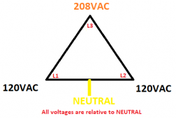
This is the 3P power provided by the Utility Company to a certain neighborhood in Manila, Philippines.
1660785739027.png
L1-L2 = 240V
L2-L3 = 240V
L3-L1 = 240V
NOTE: L3 to N is 208V, But L1 to N is 120V, L2 to N is also 120V

Some houses receive 3 wires, either L1L2N or L2L3N or L3L1N.
My apartment compound has all 4 wires.
We do not use Neutral for power. We use it solely for grounding appliances - it is by local code to bond N to a Grounding Rod.

So I connected my Inverter's (Deye) PE terminal to Ground.
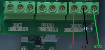
I also connected L1 and L2 as shown on the L and N terminals.
NOTE: All PE in this terminal block are connected to each other and also connected to Case.
1660787064040.png


Here is my Question:
It was said that during a Utility Outage, I need to disconnect Utility's Neutral to Inverter's Neutral.
BUT all PE are connected on this terminal.
Likewise N on this terminal is connected to L1 (not N).

What now?
 
So they use High-leg delta with stinger leg.

Does this inverter has relay that will tie N terminal to PE on the Load terminal when it is in inverter mode?
If you check the resistance between the Grid N terminal and the Load N terminal, does it show <1 Ohm (meaning the N is pass through, check it with nothing connected to the unit)?
 
I forgot to mention:
Even though the compound is wired 3P, individual units are single phase receiving 120-0-120, or 120-0-208V, with the exception of my Brother-In-Law's Brother who is wired 3P. My unit there in is 120-0-208V. I simply wanted to point out that, HOT-Neutral-HOT is not 120V-0-120V.

Does this inverter has relay that will tie N terminal to PE on the Load terminal when it is in inverter mode?
If you check the resistance between the Grid N terminal and the Load N terminal, does it show <1 Ohm (meaning the N is pass through, check it with nothing connected to the unit)?
This is a Single Phase 5KW Deye (similar to SunSync or Sol-Ark)

On this particular inverter, the PE terminals are connected (on the PCB) to each other.
All N terminals are completely isolated from PE.

1660790455689.png

Nonetheless, I will repeat measuring these terminals on difference scenarios.

RESULTS
Deye OFF: LOAD L to GRID L = open, LOAD N to GRID N = open
ON - no Grid Power: LOAD L to GRID L = open, LOAD N to GRID N = open
ON - GridTie (GRID CB=ON): LOAD L to GRID L = closed, LOAD N to GRID N = closed
This confirms the initial findings

Deye's default is Open Circuit for the relays.


I did one more test:
Set Deye into Zero Export To Load and measured the Terminals:
1660820050314.png
I could not get a good reading. Unlike previous readings that are either zero ohms or open,
this time I am getting somewhere from 100ohms to kiloohms.
 
Last edited:
One of the phase winding as shown in the drawing has center tab so you basically has 240V split phase, in your usage you have two hots so that inverter should have been labeled with L1, L2, PE instead of L, N, and PE. When it is labeled with 'N' it will make you think you can bond N and PE as needed, in this case if you tie N (which is L1 as you show) to PE you short out L2 to N which has 120V potential, this unit is made for single phase not made to be fed with two Hots.
As far as the Load concerns, it will see 240V, it is when N of this unit is bonded to PE in this case it'll have problem because N is actually L1 in this case.
 
Last edited:
Actually it's not split-phase. It's two legs of a 3-phase high leg system. And a ground wire. (For this service)
Which is Single phase 240v.
This grid structure can provide five types of services.
Single phase 120v
Single phase 208v
Single phase 240v
3-phase (high leg) 240v
Split-phase 240/120v
It's used widely because of its versatility.
I use the word split phase on one of the winding that OP wants to use because it has center tap which is Neutral (L1 - N = 120V, L2 - N = 120V) and also tied to Ground at that point as shown in the diagram which makes it easy see what will happen when N terminal of the inverter is Bonded to PE since N of the inverter is not really N, OP is not using the other phases. Yes, It's used widely because of its versatility.
Notes: sometimes I have a hard time explaining things in English as to what I am trying to say.
 
Last edited:
Back
Top