


You are using an out of date browser. It may not display this or other websites correctly.
You should upgrade or use an alternative browser.
You should upgrade or use an alternative browser.
Easun (and others) 6048 charger smart interface
- Thread starter profesor79
- Start date
I had luck yesterday, no sunshine at all, so i could make the swap without losing solar energy. The next task would be to verify if my original MPPT (which looks the same as Easun but it's branded PowMR) uses the same protocol. It could be different as the menu and the displayed informations are not 100% the same, for instance it displays incoming solar power not just voltage.
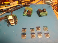
You need to reflash all those MCUs? I prefer to buy Tasmota compatible devices or ones which has pin compatible Tuya MCUs with ESP12 so i can make a swap (like Tuya WBR3 -> ESP12F).
You need to reflash all those MCUs? I prefer to buy Tasmota compatible devices or ones which has pin compatible Tuya MCUs with ESP12 so i can make a swap (like Tuya WBR3 -> ESP12F).
profesor79
...
I made a decision to reflash them all. It is one-off operation. What cameout of this operatin that some of the sockets are using esp8266, but the firmware was upgraded so was not able to do cloudcutter on them.I had luck yesterday, no sunshine at all, so i could make the swap without losing solar energy. The next task would be to verify if my original MPPT (which looks the same as Easun but it's branded PowMR) uses the same protocol. It could be different as the menu and the displayed informations are not 100% the same, for instance it displays incoming solar power not just voltage.
You need to reflash all those MCUs? I prefer to buy Tasmota compatible devices or ones which has pin compatible Tuya MCUs with ESP12 so i can make a swap (like Tuya WBR3 -> ESP12F).
For ESP will use ESPHome, as was struggilng with Tasmota to get the devices configured (like relay pin was not provided on the config screen).
The goal of this is to dynamically switch on my second inverter during a day time, or swich invertes during night time, so the socket need to ask HomeAssistant if a particular load (2kW kettle, grill or other stuff) can be switched on. It is a kind of crazy setup, but we need to save energy especialy in winter time.
profesor79
...
hey
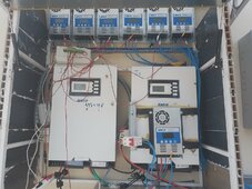
I had to re-do my board as did it without proper electrical connections
Tonight I installed it - and will be working on nice dash to see how it is going.
But for now my 6 charge controllers are visible in Home Assistant.


I had to re-do my board as did it without proper electrical connections
Tonight I installed it - and will be working on nice dash to see how it is going.
But for now my 6 charge controllers are visible in Home Assistant.
profesor79
...
There is no modupus port on this charger... there is no port at allHmm, why not just ask the manufacturer for the modbus protocol ? Or maybe I am just missing something .
")
profesor79
...


profesor79
...
hey
no I did not see the data, maybe if I will have more time that could be possible.
But from other way, as absorption and floating are voltage based modes, then it could be managed by received data.
no I did not see the data, maybe if I will have more time that could be possible.
But from other way, as absorption and floating are voltage based modes, then it could be managed by received data.
computingcode
New Member
Hello,
If it's not too much bother or too much to ask for, can you please post the wiring diagram for what you did? From what I understand you read the Serial information off the LCD's ribbon, but it is unclear what pins you intercepted. Same for the RS232 implementation.
Regards
If it's not too much bother or too much to ask for, can you please post the wiring diagram for what you did? From what I understand you read the Serial information off the LCD's ribbon, but it is unclear what pins you intercepted. Same for the RS232 implementation.
Regards
profesor79
...
heyHello,
If it's not too much bother or too much to ask for, can you please post the wiring diagram for what you did? From what I understand you read the Serial information off the LCD's ribbon, but it is unclear what pins you intercepted. Same for the RS232 implementation.
Regards
i don't have access to device as they are working now.
But in this post: https://diysolarforum.com/threads/easun-and-others-6048-charger-smart-interface.74826/post-964896 there is a photo of the back of the LCD screen with + and - markings. The TX pin shall be next to "-", so you could try that. The wires are connected to two separate RS232 to TTL modules, that mean you have all is needed theree.
You only need 2 pins from the display: GND (which is common ground with the converter) and TX (connected to the RX on the receiver side).Hello,
If it's not too much bother or too much to ask for, can you please post the wiring diagram for what you did? From what I understand you read the Serial information off the LCD's ribbon, but it is unclear what pins you intercepted. Same for the RS232 implementation.
Regards

profesor79
...
You only need 2 pins from the display: GND (which is common ground with the converter) and TX (connected to the RX on the receiver side).
When you provide a power supply from connected device and connect directly to arduino/esp.
Hello, based on your work I have made esphome component @ https://github.com/MirecX/easun6048
It calculates also power based on battery voltage and current

however, sometimes broken packet arrives and data are innacurate!
I am using esp32 devkit v1 fully powered by lcd port, maybe some EMI is causing the bit flip. I have to investigate further.

********************************
Late night update:
LCD 3.3V line is weak for esp32.
ESP32 while powered from dedicated usb adapter, has flawless flowing serial data:
 ********************************
It calculates also power based on battery voltage and current
however, sometimes broken packet arrives and data are innacurate!
I am using esp32 devkit v1 fully powered by lcd port, maybe some EMI is causing the bit flip. I have to investigate further.
********************************
Late night update:
LCD 3.3V line is weak for esp32.
ESP32 while powered from dedicated usb adapter, has flawless flowing serial data:
********************************
Last edited:
Similar threads
- Replies
- 1
- Views
- 122
- Replies
- 1
- Views
- 246
- Replies
- 4
- Views
- 839