diy solar

diy solar

EASUN IGRID VE II 5,5KW (Sorotec REVO II ) GERMANY firmware "Utility Power charging disabled" ?

Technically it is possible
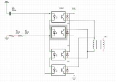
They have a CT clamp to prevent back feeding
If we can trick the CT clamp that there is load, than the inverter will provide current
We know it's technically possible.
It was available, they took it out.

The CT clamp isn't the problem, the solar part is, if you want to trick something.

It still can feed to the grid, but only from solar, right?

I don't have grid, so I can't play with it.
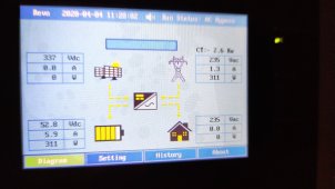
I don't know if it only starts to feed the grid after the batteries are fully charged, and at what depth of discharge it will start recharging again.

One "dirty" way is to trick the solar.
DC=DC.. no wave length to match.
Disconnect the solar and connect the battery as "solar".
Sure, you will need a voltage booster, that's about it.

Other way, probably cheaper then a voltage booster, is an "grid only" inverter.
Who works with the 50v "solar" it's being given.

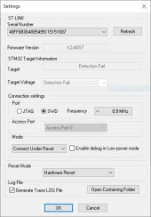
Simply "trick" the Revo firmware to act in a way they no longer designed it...
Might be a lot more complex than you think!

Alterative would be that Sorotec would provide the old firmware.
It was built inside.
The first one had several bugs..
Probably more a pain then that it is worth it, to "re-activate" this code.

Last alterative I can think of..
We have the firmware.
Perhaps someone with programming skills can put it back in?

Cheapest and fastest solution would be an grid tied inverter.
Micro inverter work with 18-50v, 2 in series :)
500w is about €75, so for €150 you feed 1 kWh.

Assuming it is all solar overproduction and you have enough capacity.
Assuming the high electricity price of € 0.75 per kWh, this investment is earned back in 9 days. (When feeding 24/7)

Arduino and a contractor should be able to let you program it, add another €50.

€18 per day... That's not a bad return...

Just brainstorming here

I hope it works out for you guys!
 
The CT clamp isn't the problem, the solar part is, if you want to trick something.
Assume you have no load
If you can trick the CT clamp and let the inverter believe that the CT clamp is reporting 500w
The inverter will push out 500w
So then you are back feeding 500w to the grid

So I think tricking the CT clamp is the easiest way of backfeeding
 
Assume you have no load If you can trick the CT clamp and let the inverter believe that the CT clamp is reporting 500w The inverter will push out 500w So then you are back feeding 500w to the grid So I think tricking the CT clamp is the easiest way of backfeeding

CT clamp is a simple "hall sensor", and easy to "mimic" (or trick).
The CT clamp is measuring the amount of energy going in and out.

To my understanding, when the battery is fully charged, the excess energy created via the solar panels is being feeded to the grid.
As result, to get "excess energy" to the grid, is to first "mimic" a fully charged battery.

The power stored into the battery can (at this moment) only be used after being inverted for the power out cable.
As it was possible in the past, it makes sense that it would at the same frequency. It's not 100% certain. (!!!)
If it is same same, then you would be able to feed from the power out to the power in. If it isn't... magic smoke

It will take a few steps, battery first needs to be seen as fully charged.
Second step is indeed the hall sensor, you simply can measure the millivolt output differences when charging from the grid, doing nothing, and feeding to the grid.
I would expect that the Revo uses that information to "calculate" the amount of ampere being fed to the grid.
I'm not sure what will happen when you tell the Revo by providing the exact information (voltage) that the Hal sensor sends out to the Revo normally, when feeding to the grid, say 10A ( 2200 watt)

Will it start taking energy from the battery?
Or only feed excess energy from the solar?

Please do try, and keep us informed!!!
 
CT clamp is a simple "hall sensor", and easy to "mimic" (or trick).
The CT clamp is measuring the amount of energy going in and out.

yes that is possible with 4 optocouplers as H-bridge
the 3,3V is just the PWM output (raspberrypi in my case) with a fat elektrolyt condensator
the 2 coils is just an old transformator 230V/24V (so ratio is 10:1)
the 24v output connect to the CT input of the inverter
to reduce the needed current 2 smd resistors in the CT input in the inverter needs to be desoldered
PWM value 30 is then 1800W fo the inverter
will publish py code to github
 

Attachments

  • conv.JPG
    conv.JPG
    83.8 KB · Views: 5
Hi, in the meantime EASUNchat (seems to be avy@easunpowert.com) gave me this reply:
"View attachment 114698
But i am still skeptical as i read about this limitation (based on specific german "EEG regulations") in a german translation of the IGRID TT 10 kW manual.

At this moment i am not able to test the function (still waiting for my 16S 302Ah LiFePo battery to arrive).
The installed LCD Firmware Version is V1.4.8 2022-04-15.


View attachment 114699

Can you imagine this is a special restricted firmware version adapted for this crazy german restriction ?
(imo this is not typical chinese-style behavior)

Based on good software development practice, imo there sould be a factory-level-based modification of this setting.

But, in the case of the need to get rid of this german-restricted firmware version, how to flash just the LCD firmware without endangering the rest?

I have this problem now.

LCD Version: V1.5.1 2022-07-01
Inverter Version: V1.5.4 2021-07-19
Mppt Version 1.4.4 2021-12-02

My Revo II does not feed any power to the grid/power to loads connected to "AC Input" - direction (+ or -) of CT sensor does not change anything.
Option "On Grid" and Switch on bottom of inverter also does not change behaviour.
Hello @FMode ,

Welcome to the forum.

You have this problem "now" ...
= That it worked before as you liked but now stopped working?

The switch on the bottom of the inverter is the power on / off switch.

If that doesn't change any behavior, it's not turned on at all ? ????
(Just joking)

I know how frustrating it can be to get things working.

To be able to help, I need some more information:

What is your setup and what are you trying to accomplish?

Did it ever work?
Or not yet?
And what have you tried?
No the inverter is new and it never worked for me.
The inverter shows status "idle" if I turn off this switch. I do not understand this switch.

The inverter is "informed" that I am consumeing power (here 2,6kW) , the sun is shining and the battery is full so it should now push energy to "AC input" and so lower the shown CT value.
My setup is drawn in the manual at chapter 4.5 "AC Input/Output Connection" does anybody have the pdf version - the link http://easunpower.cn/uploads/soft/201207/1-20120GS916.pdf Frank posted to EAsun does NOT work anymore.

I am expecting to flash firmware and have everything ready....
 

Attachments

  • soro.jpg
    soro.jpg
    250.4 KB · Views: 7
Last edited:
No the inverter is new and it never worked for me.
The inverter shows status "idle" if I turn off this switch. I do not understand this switch.

The inverter is "informed" that I am consumeing power (here 2,6kW) , the sun is shining and the battery is full so it should now push energy to "AC input" and so lower the shown CT value.
My setup is drawn in the manual at chapter 4.5 "AC Input/Output Connection" does anybody have the pdf version - the link http://easunpower.cn/uploads/soft/201207/1-20120GS916.pdf Frank posted to EAsun does NOT work anymore.

I am expecting to flash firmware and have everything ready....

I would say, back to basics.
Aka, disconnect the grid.
Just the inverter, the solar and your power consumption.

When this is all working OK, it's time for the next step, adding the grid.

Not yet feeding to the grid as this is the very last step, and obviously depending on your country if you are able to, and your (smart) meter in your home. Not all are standard capable of feeding to the grid.

Several electricity companies you first need to contact and have inspection and so on.

Understandable.
When their people are doing maintenance on the grid and they shut their part down....
It would be nasty if your solar would fry an employee....
Safety first!!!

Anyways...
Once you have concluded that everything works and the electricity company knows...

Time to focus on feeding to the grid.

Even that first "blunt"...
Select "battery less" as battery type.
This way there is no option for a wrong setting...

Reduce you consumption to a minimal.

Your over Solar production should flow to the grid, if all setting is OK.

As there are less things that Influence, more easy to find out.

The screenshot shows that the battery is charging from the grid....
Not from the solar.

As it is charging...
It's not fully charged:)

This might be one reason why it's not sending anything to the grid yet, but ..
There are many small steps to be taken.

Start by making sure your grid can accept you to feed to it :)

This is just an example screenshot showing CT sensor works.

I can control everything also the AC input.
I can also switch off the batteries but this also does not affect the inverter to push power to the loads connected on "AC Input".

Without AC on "AC Input" the Battery is charged, without Sun the Batteries are used to power the inverter.
I don't want to feed the grid - thats why this inverter has an external CT sensor and I certainly mounted this CT sensor before the loads. ("zero feed to grid")

The 1.3 Ampere show in the example is from the internal current sensor. To compute the current of the loads the external sensor needs to be sustracted from the internal sensor.

This is 99% a software issue and not a hardware problem.
From screenshots here in the forum I can tell that i never get Status "AC+PV" only "AC Bypass" (what else that means) I also never get the arrow pointing in the direction of the grid.
 
Last edited:
This is just an example screenshot showing CT sensor works.

I can control everything also the AC input.
I can also switch off the batteries but this also does not affect the inverter to push power to the loads connected on "AC Input".

Without AC on "AC Input" the Battery is charged, without Sun the Batteries are used to power the inverter.
I don't want to feed the grid - thats why this inverter has an external CT sensor and I certainly mounted this CT sensor before the loads. ("zero feed to grid")

The 1.3 Ampere show in the example is from the internal current sensor. To compute the current of the loads the external sensor needs to be sustracted from the internal sensor.

This is 99% a software issue and not a hardware problem.
From screenshots here in the forum I can tell that i never get Status "AC+PV" only "AC Bypass" (what else that means) I also never get the arrow pointing in the direction of the grid.
Perfect!

I never said it was a hardware issue, but a software setting issue.

It looks like you have it all figured out, so not sure what you are asking for here.

As all seem to work exactly as you like??

Good for you!
Have a great weekend :)
 
Perfect!

I never said it was a hardware issue, but a software setting issue.

It looks like you have it all figured out, so not sure what you are asking for here.

As all seem to work exactly as you like??

Good for you!
Have a great weekend :)
No I did not work - it did not power anything than itself.

... until I flashed Touch-03801-14-S3.hex which is "V1.4.3 2021-05-31" to the display.
(this was a 100% "shot into the blue"!)
With a ST-LINK V2 - wo had the idea of using an expensive Segger J-Link for that ?
Be careful about the pin layout of the ST-Link V2 there are 2 versions!
The STM32CubeProgrammer seems buggy use "STM32 ST-LINK utility"
You will need SWIM_RST for NRST.
 

Attachments

  • stlinkv2.JPG
    stlinkv2.JPG
    50.8 KB · Views: 10
No I did not work - it did not power anything than itself.

... until I flashed Touch-03801-14-S3.hex which is "V1.4.3 2021-05-31" to the display.
(this was a 100% "shot into the blue"!)
With a ST-LINK V2 - wo had the idea of using an expensive Segger J-Link for that ?
Be careful about the pin layout of the ST-Link V2 there are 2 versions!
The STM32CubeProgrammer seems buggy use "STM32 ST-LINK utility"
You will need SWIM_RST for NRST.
I'm happy you fixed it.

I guess you had the idea of using an expensive J-Link?

I made a fool proof dummy step by step guide on how to flash the display firmware and provided all versions I could get my hands on.
(Available in the resource section of this forum)

Flashing the MPPT is a different story.
I ended up buying a "special version" from sorotec.
Not original Segger, also not your standard clone.
I've tried v2 up to v9 (4 different 2,5,8&9) none worked.
The one from Sorotec does.

Flashing seem to go OK, it erased.. writes, then error.
MPPT useless.

I have 6 or 7 or so spare MPPT boards, so stuff to play with.
Now they all work.

Be free to try if your Segger or standard aliX J-Link clone will work on the MPPT.

I can reflash for you once you brick it.
Or send one of my spares.

For the display...
Not a problem at all.
All 4 (+ the special one from Sorotec) flashed without any issues :)
so this idea is from sorotec! Why dont they recommend the much cheaper ST-Link???

Here is it: the ST-Link does not recognize the ST CPU on the MPPT - no communication! (this is the tool from the CPU manufacturer!)
so there is something fishy going on - be careful!
So the flasher always reports an error? It aborts the flasheing? Verify error?
Disconnect power read again it must be 1:1 what you flashed - use a file compare tool.

So the connection from the flashing connector to the CPU itself must be traced.
....

and I certainly have the next problem:
too much power to AcInput - means the external CT sensor (and my power meter) report negative Watt values means I supply power to the grid because my loads consume less than the sun delivers.
So the external CT sensor is useless.?‍♂️

and certainly the Sorotec support does not reply to me

edit:

WARNING!
My inverter has AcOut L and N exchanged check yours.
 
Last edited:
so this idea is from sorotec! Why dont they recommend the much cheaper ST-Link???

Here is it: the ST-Link does not recognize the ST CPU on the MPPT - no communication! (this is the tool from the CPU manufacturer!)
so there is something fishy going on - be careful!
So the flasher always reports an error? It aborts the flasheing? Verify error?
Disconnect power read again it must be 1:1 what you flashed - use a file compare tool.

So the connection from the flashing connector to the CPU itself must be traced.
....

and I certainly have the next problem:
too much power to AcInput - means the external CT sensor (and my power meter) report negative Watt values means I supply power to the grid because my loads consume less than the sun delivers.
So the external CT sensor is useless.?‍♂️

and certainly the Sorotec support does not reply to me

edit:

WARNING!
My inverter has AcOut L and N exchanged check yours.
For the MPPT, i can only advice not to flash it.

they provided me (for a fee) with a special clone that does work with their MPPT.
2 other clones and one original Segger bricked the MPPT boards.
With their "special" i could re-flash them and all is good.

the clones and original worked perfect on the display firmware, just not the MPPT.
all seems good, until it doesn't, and then the existing firmware is erased, and not the new firmware on there....

If anyone has this problem, I have several mppt boards for swap available, obviously you pay for the transport costs

For the CT...
I cant help you there, i'm not connected to the grid.
 
Back
Top