diy solar

diy solar

EDITED TITLE: Why not common Neutral? What is dangerous about it?

If someone is doing offgrid solar why not simply install a euro spec inverter and just build that? (Devils advocate)
Basically it wouldn’t likely happen because everything would have to ordered in from overseas on one hand. On another, neither code enforcement nor the powerco monopolies would make that jurisdictionally feasible.

The other question in my mind is (because I do not know) is does europe even use a safety ground? I can see perfectly well that a euro grid could function on two wires only, but at what point and where is/are the euro 240V lines ‘earthed?’ Because I can still see how voltage through a body to dirt or anything connected to dirt could be dangerous aka lethal. Or maybe I’m confused by the years of watching some electricians pound in multiple ground rods for generators or separate buildings with subpanels (which I now understand is wrong).
Yes, they use a grounding system.
Their power is Line and Neutral. (Neutral is a grounded conductor)
But most do the bonding at the grid side of the service. And provide a L,N,and G (known as an Earthing) conductor to the customer. In North America the utility companies decided that they could save money by not providing the G conductor to every service. And have the customer do their own bonding.
As always, money drives every decision.
 
Any time I purchase a new appliance or piece of equipment, I choose 240v if it's available. For simplicity, cost, and efficiency. I would go 3 phase if it were feasible for residential. And still might.
 
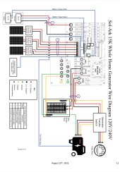
I am going to parallel inverters (however only one inverter shown in the following diagram), but I will have a transfer switch. Right now ground and neutral are bonded at the transfer switch, but according to the diagram, the bonding is in the main panel. Which is correct?

Edit: Sol-Ark tech said it doesn’t matter, as long as there is only one bond.

712C8167-5940-44A0-9F3B-E1714767EEBA.jpeg
 
Last edited:
I am going to parallel inverters, which is not in the following diagram, but I will have a transfer switch. Right now ground and neutral are bonded at the transfer switch, but according to the diagram, the bonding is in the main panel. Which is correct?
“Correct “ depends on whether that’s grid tied or not, and whether the system is wired to obtain the N-G bond from the entrance panel even when disconnected from the grid. Sorry, I didn’t study the diagram and I’m probably not qualified to answer as an electrician.

Nevertheless, from my brief view and your wording I’d GUESS that “correct” would N-G in the “main panel” provided- whether grid or inverter mode- there is only one N-G circuit in the system at one time.
If the xfer switch switches N and G that’s a different situation to address.


Edit: Sol-Ark tech said it doesn’t matter, as long as there is only one bond.
Correct, Solark ties the two neutrals together internally. Solark *always* runs in a comon neutral configuration so there only needs to be a single bond in the whole system. If the uniti is tied to the grid it will typically be at the main breaker box.
 
I have a grid and offgrid load panel, (2) 6500s. Offgrid panel no NG bond. Grid panel NG bonded.

If I remove the bonding screws in both 6500s, then bond the offgrid panel neutral to the grid panel neutral to make them common, this would seem to put my particular system in line with the new guidance and the example of Sol Ark above, correct?
It is in line with sol ark..... but Solark does not switch neutral. The 6500 does switch neutral so there really is no comparison between the solark and the 6500 when it comes to bonding.

Unfortunately, EG4 made the change to the bonding but has given NO guidance. From all reports, your arrangement works. Furthermore, your arrangement gets the neutral-ground bonding correct. What is still an open question is whether a common neutral is supported by EG4. In previous messaging, we have been told it is not supported, in fact, we have been told it is unsafe... And that brings us back to the very first post on this thread.

IMHO, the way you are set up is the way I think ALL inverters should support stationary installs. Dynamic bonding should only be used in mobile installs.

<Insert here: one of my many long-winded rants about how horrible the documentation is on these inverters>
 
Last edited:
I sent an email to EG4 support detailing my concerns and recommending immediate action on their part. My hope is that my letter will make a difference.... my fear is that they will continue to ignore the problem. (I first started communicating the issues to them in May of 2022)

At a minimum, they need to make clear statements on support (or not) for common neutral arrangements and support (or not) of customers removing (or adding) the bonding screws. (They currently state that the user can remove the screw if the installer provides documentation of the need to the distributor. This is kinda wishy-washy, but I guess it is better than nothing)

I hope their statement will be that common-neutral is supported. This would provide the ability to properly set up the inverter for all stationary installations as long as they are allowed to remove the bonding screws (if present). In order to support mobile installs, they will need to provide ways for the user to add or remove the bonding screws.
 
It comes to mind:
If the EG4, MPP AIO inverters' N-G bonding screw "should not be removed" as it would be "unsafe", then WHY is this a removable screw in the first place, and why in the second place is it placed neatly in line with a dedicated hole in the circuit board that allows removal?
 
It comes to mind:
If the EG4, MPP AIO inverters' N-G bonding screw "should not be removed" as it would be "unsafe", then WHY is this a removable screw in the first place, and why in the second place is it placed neatly in line with a dedicated hole in the circuit board that allows removal?
This is standard practice for Bonding boards to metal enclosues. There are other Bonding screws on this and other boards, in these units, also. The screw in question just happens to be the one that is also used for the N/G bonding relay.
 
It comes to mind:
If the EG4, MPP AIO inverters' N-G bonding screw "should not be removed" as it would be "unsafe", then WHY is this a removable screw in the first place, and why in the second place is it placed neatly in line with a dedicated hole in the circuit board that allows removal?
That is a very good question....... and part of why I started this thread.

One of the problems we are dealing with is that these inverters are all designed and built by a Chinese ODM, not EG4, MPP, Growatt, etc. That means there is a significant distance between the engineers that designed the product and the companies that are branding the product. My suspicion is that common neutral is in fact perfectly safe, but that fact is getting lost someplace between the original engineers that designed the product and the people selling the re-branded product.

Note: I understand the reluctance to let customers open up the system and muck around inside, but since they advertise these as stackable, they need to provide the customer a way to stack them safely.... and that requires mucking with the screws and/or common neutral.
 
There are other Bonding screws on this and other boards, in these units, also. The screw in question just happens to be the one that is also used for the N/G bonding relay.
Perhaps, but none that are as clearly positioned as the screws in question, behind an obvious access hole to get to it, at least not on the 6048.
check it out:
First pic showing the AIO opened up and the two clearly seen access holes, and the second pic is what you see if you look right at one of the access holes, complete with a little pic of a screw and Gnd symbol in case there was any doubt what this screw is about.
To me it is pretty clear "they" (board designer) intened to allow easy access to the bonding screws, even while these are behind another board, and the holes allow this to be done without removal of any wires or boards, only the main panel cover - which I just flipped up onto the top of the AIO so I didn't even need to unplug the display.
 

Attachments

  • IMG_4346_compressed.pdf
    189.5 KB · Views: 12
  • IMG_4349_compressed.pdf
    116.1 KB · Views: 9
I don't know anything about the holes. But all mounting screws that pass through a trace are identified with a ground symbol.
 
these inverters are all designed and built by a Chinese ODM, not EG4, MPP, Growatt, etc. That means there is a significant distance between the engineers that designed the product and the companies that are branding the product.
It was my understanding (not confirmed) that MPP Brand inverters, are made by Voltronics, who in turn also make other very simialr inverters. Voltronics have factories in Taiwan, mainland China (Shenzen), and Vietnam that I am aware of, and claim on their website to not outsource manufacturing.
I wonder if we could ask Voltronics about the design, and stacking concerns, how to safely deal with neutrals and the bonding screws.
 
It was my understanding (not confirmed) that MPP Brand inverters, are made by Voltronics, who in turn also make other very simialr inverters. Voltronics have factories in Taiwan, mainland China (Shenzen), and Vietnam that I am aware of, and claim on their website to not outsource manufacturing.
That is in line with my understanding. Voltronics is the ODM (Outside Design & Manufacturer) for MPP, EG4, Growatt, SunGold, etc. They have one design that gets used for all of the brands, but sometimes the design will get minor tweaks based on th the requirements of the branding company. (EG4, had them do several tweaks for the 6500. However, the Sungold and Growatt equivalent inverters are so similar you can swap the firmware between the two.
 
Perhaps, but none that are as clearly positioned as the screws in question, behind an obvious access hole to get to it, at least not on the 6048.
check it out:
First pic showing the AIO opened up and the two clearly seen access holes, and the second pic is what you see if you look right at one of the access holes, complete with a little pic of a screw and Gnd symbol in case there was any doubt what this screw is about.
To me it is pretty clear "they" (board designer) intened to allow easy access to the bonding screws, even while these are behind another board, and the holes allow this to be done without removal of any wires or boards, only the main panel cover - which I just flipped up onto the top of the AIO so I didn't even need to unplug the display.
It is fun to speculate.... but without hearing from the original engineers it is just speculation. However, the fact that they are now shipping without the screws is a strong indication that the original design was done with this as a possibility. Taking that a step further, If the original design allowed for shipping without the bonding, it implies the original design would work with a common neutral because there are very few configurations where you can safely set the system up without the bonding screw and without a common neutral.
 
Back
Top