Maybe you have an idea what went wrong ? Bms failure … ?
It’s in a bus ?
I have x2 24v packs connected togther.
So x2 bms. One on each bank.
System seemed to work okay for about 2 weeks.. and suddenly on an afternoon parked under a tree for about 5days not moving..
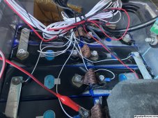
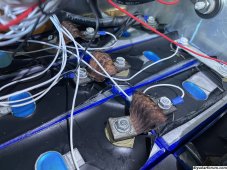
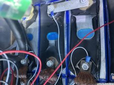
I smells nothing strange.. not sure what it was .. few days later opened the battery box melted casings on all the batterys.
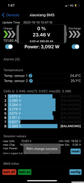
Battery bank shut down. X2 cells reading 0.2 or something dead flat.
what seems to be happening is one bms. Is charging its battery bank from the other. (As I have no power input from solar or anything at this moment in time)
Is the bms meant to do that ? Or is the bms faulty
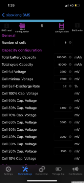
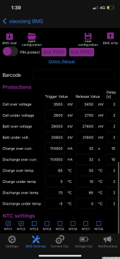
See photos for bms settings and damage.
I have since removed the positive cable connecting this bank to the other.. my other bank seems to work as it should.
But now I don’t know what to do with this one where to start.
There are no shorted cable points or weld marks on connectors wires don’t appear burnt out or anything it just got Uber got it the box and yeah I mean I thought the bms would shut down over temperature ?
?
I tried charging one of the dead cells with a desktop charger.. it seems to be okay the other one not.
The strange thing is the two dead cells are not melted all the other okay cells are melted
View attachment 171626

It’s in a bus ?
I have x2 24v packs connected togther.
So x2 bms. One on each bank.
System seemed to work okay for about 2 weeks.. and suddenly on an afternoon parked under a tree for about 5days not moving..
I smells nothing strange.. not sure what it was .. few days later opened the battery box melted casings on all the batterys.
Battery bank shut down. X2 cells reading 0.2 or something dead flat.
what seems to be happening is one bms. Is charging its battery bank from the other. (As I have no power input from solar or anything at this moment in time)
Is the bms meant to do that ? Or is the bms faulty
See photos for bms settings and damage.
I have since removed the positive cable connecting this bank to the other.. my other bank seems to work as it should.
But now I don’t know what to do with this one where to start.
There are no shorted cable points or weld marks on connectors wires don’t appear burnt out or anything it just got Uber got it the box and yeah I mean I thought the bms would shut down over temperature ?
?
I tried charging one of the dead cells with a desktop charger.. it seems to be okay the other one not.
The strange thing is the two dead cells are not melted all the other okay cells are melted
View attachment 171626