Reading 16 holding registers at a time while the battery breakers are off and the inverter is not connected yields this. The first three bytes of each response are client ID, function code, and length. The last 2 are the CRC:
2023/08/02 20:08:02.715593 Sending: 0103000000104406
[1] 2023/08/02 20:08:02.766851 010320 0000 0000 0000 0000 0000 0000 0000 0000 0000 0000 0000 0000 0000 0000 0000 0000 927a
2023/08/02 20:08:02.766910 Sending: 01030010001045c3
[2] 2023/08/02 20:08:02.818070 010320 0000 0000 0000 0065 0000 0043 14b3 0000 0021 2710 3458 4e20 0204 0000 0006 0000 bede
2023/08/02 20:08:02.818121 Sending: 01030020001045cc
[3] 2023/08/02 20:08:02.869497 010320 0000 15e0 0000 4e20 0000 0cf7 0cec 0001 0001 0010 0000 0000 0000 0000 0000 0000 ee7e
2023/08/02 20:08:02.869578 Sending: 0103003000104409
[4] 2023/08/02 20:08:02.920844 010320 0000 0000 0000 0000 0000 0000 0000 0000 0000 0000 0000 0000 0000 0000 0000 0000 927a
2023/08/02 20:08:02.920886 Sending: 01030040001045d2
[5] 2023/08/02 20:08:02.972166 010320 0000 0000 0000 0000 0000 0000 0000 0000 0000 0000 0000 0000 0000 0000 0000 0000 927a
2023/08/02 20:08:02.972248 Sending: 0103005000104417
[6] 2023/08/02 20:08:03.023584 010320 0000 0000 0000 0000 0000 0000 0000 0000 0000 0000 0000 0000 0000 0000 0000 0000 927a
2023/08/02 20:08:03.023671 Sending: 0103006000104418
[7] 2023/08/02 20:08:03.074998 010320 0000 0000 0000 0000 0000 0000 0000 0000 0000 0000 0000 0000 0000 0000 0000 0000 927a
2023/08/02 20:08:03.075081 Sending: 01030070001045dd
[8] 2023/08/02 20:08:03.126404 010320 0000 0cec 0cf7 0cef 0cf1 0cef 0cf1 0cf2 0cf0 0cee 0cf0 0cf0 0cef 0cf0 0cf2 0cf0 56ba
2023/08/02 20:08:03.126484 Sending: 01030080001045ee
[9] 2023/08/02 20:08:03.177767 010320 0cef 0000 0000 0000 0000 0000 0000 0000 0000 0000 0000 0000 0000 0000 0000 0000 e593
After that point, the requests don't get a response which means that only registers 0 thru 144 are available, I guess.
The inverter only reads the 16 registers starting at position 19, first one being that 0065 row 2, in bold, and we know that in the same row the 0043 is SOC (67%), and the 14b3 is 10mV (5299 -> 52.99V), and my guess these two numbers are aggregated from all the batteries. not just ID 1.
After all the zeroes there's a surprise in line [8], which is reading 16 registers starting at address 112. The 16 registers starting at address 113 represent the mV of each cell for the master battery! (0cec -> 3308mV -> 3.308V) and so on.
[Edit] 0cf7 0cec in line 3 looks like highest and lowest mV across all cells(?).
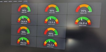
At least I can export to home assistant the voltage of all cells in all batteries, while still using the EG4 protocol for inverter to battery comms. This is progress!
P.S.: btw, it doesn't matter which ethernet wires I use for RS485. Both{1,2} as inverter does or {7,8} as the battery comms cable does "speak" the same protocol and get "angry" if you use both of them at the same time.