rebible
New Member
The problem:
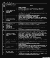
when the system switches to the generator (utility) at least one inverter will throw a F60 power feedback error within the first 1/2 hour of running off the generator.
System:
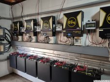
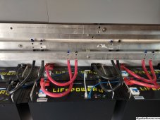
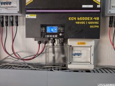
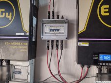
is 4 inverters split phase , 12 eg4 batteries (60Kwh), gobs of solar, and a 20KW generator.
The generator is a new Kohler.
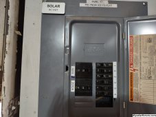
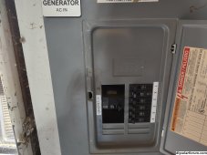
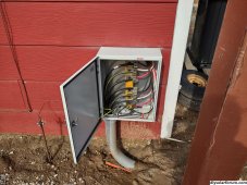
The wiring is "textbook" clean with over sized conductors used everywhere.
While on solar or battery the system seems solid with minor flickering on some LED lights and occasional ups alarm beeps. Pretty much what we expected:
Current is shared as it is supposed to be and the voltage regulation is good .. As a side note the flickering is also almost eliminated with 4 vs 2
Inverters are programmed SBU and 50 amps charge from utility.
BUT,
if the system tuns on the generator with the NO contacts (or we manually have the generator already running) within about 1/2 hour 1 inverter on each phase will set the F60 fault and shutoff charging and output. The other two inverters keep running but the battery charging rate is now 50% and a total system shut down and restart is necessary to get everyone happy again.
If we run the same experiment with just two inverter everything is honky dory.
I have put in a trouble ticket to signature. The units have only been in use about 1 month, but this seems like a design bug in the software.
From what I can determine the current sharing between the units in parallel is accomplished by adjusting the unit output voltages. (If you isolate one inverter from the load it slowly goes to 130V while the unit under load drops to 110V). Evidently with the utility input from a generator the current sharing feedback loop glitches.


