diy solar

diy solar

EG4 Wallmount Batteries - wiring design

MaikaiLife

Solar Enthusiast
Joined
Nov 16, 2022
Messages
650
Location
North Las Vegas
In this thread, I'm looking to get the juices going and see what people thing about the ideas below.

According to the manual, when using internal bus bars, the maximum number of EG4 wall-mount batteries that you can connect to a single 18Kpv is three.

The reason for the limitation of three on the internal bus bar is that there are simply not enough ports.
1719931974848.png

However, you can use an external bus bar to connect more.

1719931896758.png

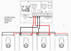
A client has asked for a proposal to provide (4x) EG4 wall-mount batteries and a single 18Kpv inverter. In order to support this configuration I have devised a rough schematic of how I would create an external bus bar, using a Victron Distributor.

1719932108708.png

My question is, do you see any issues with this configuration, and if I theoretically wanted to expand the batteries to 8 on a single 18Kpv would it be as easy as doubling the Victron Distributors by connecting them via their back-planes?

Hoping to get the juices going with some ideas and feedback. Much appreciated.
 
Why not connect to the open ports in the side batteries? The internal bus bars are good for 600A and the interconnect cables are good for 200, no need for externals and extra fuses and such (batteries have breakers).
 
My question is, do you see any issues with this configuration, and if I theoretically wanted to expand the batteries to 8 on a single 18Kpv would it be as easy as doubling the Victron Distributors by connecting them via their back-planes?

Hoping to get the juices going with some ideas and feedback. Much appreciated.

I do not see an issue using this configuration.
 
No need for the busbar, connect 2 of the batteries to one set of inverter terminals and connect the other 2 batteries to the other set of inverter terminals.
You will need one parallel set of cables for each pair of batteries too.
 
No need for the busbar, connect 2 of the batteries to one set of inverter terminals and connect the other 2 batteries to the other set of inverter terminals.
You will need one parallel set of cables for each pair of batteries too.
If it were as simple as that, no extra equipment needed I'm guessing there is a reason EG4 didn't list it in their possible configurations?

I like the idea, I'm wondering if there is something missing in that configuration.
 
No need for the busbar, connect 2 of the batteries to one set of inverter terminals and connect the other 2 batteries to the other set of inverter terminals.
You will need one parallel set of cables for each pair of batteries too.
For illustrative purposes, this is what you're suggesting with the included 0/2 AWG cables?

1719968107269.png
 
Last edited:
I like it so far, but if you had say two of the 4 batteries off, couldn't you have a condition where you're pushing nearly 200 amps through 0/2 AWG cable that would exceed its ampacity?

Something like this? I guess then you would need to always make sure each pair of batteries is enabled to ensure the current is balanced.

1719969142768.png
 
I like it so far, but if you had say two of the 4 batteries off, couldn't you have a condition where you're pushing nearly 200 amps through 0/2 AWG cable that would exceed its ampacity?

Something like this? I guess then you would need to always make sure each pair of batteries is enabled to ensure the current is balanced.

View attachment 226184
So double up on the parallel cables. You can always find a corner condition where only one battery is on or maybe none, but that’s pretty unlikely.
 
So double up on the parallel cables. You can always find a corner condition where only one battery is on or maybe none, but that’s pretty unlikely.
Yeah I was thinking that, the only question is can I get two ring terminals on there since there is no way to fit that much cable under the terminal block? Do you have any photos of how you could attach two ring terminals, I've not taken this part of the 18K apart to see what could be added.

1719970292753.png
 
Yeah I was thinking that, the only question is can I get two ring terminals on there since there is no way to fit that much cable under the terminal block? Do you have any photos of how you could attach two ring terminals, I've not taken this part of the 18K apart to see what could be added.

View attachment 226185
No, don’t double up on the battery->inverter cables, one pair is all you’re going to get.
Double up on the inter-battery cables. Remember the busbars on the batteries are good for 600A
 
No, don’t double up on the battery->inverter cables, one pair is all you’re going to get.
Double up on the inter-battery cables. Remember the busbars on the batteries are good for 600A
I don't understand why you would double up on cables between the batteries, otherwise, I presume EG4 would have had that in their diagram since they have the connection between the batteries the same. I'm concerned when you have the amperage of two batteries flowing through a single 0/2 gauge wire to the inverter, that's where I see the potential issue if the current isn't balanced between the two sets of batteries. Am I thinking about this wrong?
 
What about putting 2 parallel cables between the sets of two batteries therefore current would still be shared between the 2 cables going to the inverter?

I have 3 of the batteries wired per the manual but would like to ad 1-2 more eventually. A factory bus bar setup would be a nice addition to the eg4 lineup. Or recommended wiring without.
 
(nit: 2/0 cable)

Here are the ratings from the 18kpv terminals table. The 90C to me says that 200A through 2/0 is probably fine.

1719972149984.png

For the concern about amperage of two batteries going through a single 2/0. There is an official three battery setup. I think this layout guarantees that there are ~400A of cables going through the 2x 2/0 to the center battery's busbar. Since the inverter can at most send 250A to the battery, this is pretty overkill and safe.

I think for a 1 inverter 4 battery setup, you might need to cap the inverter to 200A to handle the worst case battery failure case. OR make bigger gauge cables with the connector, if compatible. Some old threads here says 2/0 is the limit.

OR configure per-battery BMS to a lower current limit, such as 100A charge/discharge. I am not sure if this is code compliant, it will protect the cable, but may cause the inverter to fault out.

In principle the inverter programming could theoretically know the topology of the busbar and ramp back the maximum charge/discharge, but who knows if they will implement this.

I believe the BMS on the wall batteries caps out at 200A, so that says to me 2/0 is big enough for connecting a single battery at the "end" of the topology.

What are the supported UL9540 configs? If that is important. It might just be the three battery case

1719972427388.png
 
What about putting 2 parallel cables between the sets of two batteries therefore current would still be shared between the 2 cables going to the inverter?

I have 3 of the batteries wired per the manual but would like to ad 1-2 more eventually. A factory bus bar setup would be a nice addition to the eg4 lineup. Or recommended wiring without.
Do you mean, since the middle 2 batteries have 2 spare ports each, connect those batteries together directly with 2/0?

Referring to the picture in #6. I think this effectively makes the two inner batteries have a ~400A busbar between the two inner busbar, which then have 400A up to the inverter.

(I didn't redraw the picture to add these links, just posting to show the utilization of ports)

1719973481576.png

That probably maths out.
 
I suppose you could put just one parallel cable across the two center batteries.
You mean a single +/- pair of 2/0 instead of doubling up? That probably works since the point is to get a path to the inverter cables on the other battery. I suspect the fact that inverter caps at 250A and there are 2*195A paths (before temp derating) means that even with some resistance difference between the paths each cable carries well below their limit in all cases.

It would be nice if EG4 can confirm this as a possible config (albeit maybe not safety tested).
 
Okay, so I stepped away for an hour and ya'll kept it rollin.. good stuff (y) (y)

I believe this version of the diagram, refined through several iterations, is the one that best accommodates all variables.
1719978771195.png
 

Attachments

  • 1719978754952.png
    1719978754952.png
    341 KB · Views: 0
I suspect this approach can be inductively extended to an arbitrary number of batteries, until the increasing available fault current on the bus causes something bad to happen or the probability of a problem happening goes way up with how many wires are daisy chained
 
At some calculated point there probably should be fuse involved. That is where a bus bar with individual fuses for each wire coming off it would be most protected.
 

diy solar

diy solar
Back
Top