diy solar

diy solar

EMT conduit from outside to inside. How??

Thanks for your reply. The issue I have is each mppt controller is max 250V. While that allows for 500V max, it doesn't allow for a 9s configuration at approx 50V VOC each.

The LV6548 has 2 SCC's, you can run a 4S string into one and 5S into the other but you need to run the 5S string VOC thru the calculator and determine if you might exceed the 250VOC limit on the SCC. Most likely you will, I know the 530W panels I have were 49.3VOC and 5S would exceed the limit without any cold weather.
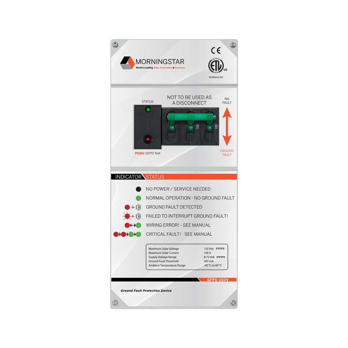
I've just thought about doing 5s and 4s without combining them in parallel. However, I am using a 2 pole GPPD device.

What is a GPPD?
I have no idea how (or if) that would work. I'm assuming not but I've emailed the manufacturer. They (Morningstar) are pretty good at their help but of course don't expect a reply over the weekend.
Regarding my last question, I'm not sure how the PV wires attach to the wires from the LV6548. Would I use wire nuts?

I wouldn't use wire nuts on pv.
And finally, any ideas about what kind of junction box I should use where the PV wires enter the inside of the house?

Why do you want a junction box? If you want a disconnect, use a IMO disconnect like the one in this video.

Run the wires into the house in conduit, here I used SCH80 pvc to just inside the house, then a simple metal box with EMT on the other side. The box is just a pass thru transition to EMT. Wires run straight to the IMO disconnect in EMT, from the IMO disconnect thru EMT and even another pass thru metal box to make a sharp corner and to the SCC's. All connections are at a terminal, no splices, no wire nuts, everything is secure. Inspectors like that type of connection.

Can it be a simple metal junction box and wire the PV wires together using wire nuts?
Thanks for your help!!
Over 36 years in business come January, I can tell you that if you spend a little extra at the onset, it pays dividends down the road. Instead of wire nuts, use a Polaris connector or terminal block where you will be carrying higher DC voltage. These connections can get quite warm if there is much resistance in a DC circuit and resistance will most likely increase as time goes on. My preference is a terminal block, either part of a switch/disconnect or an encased junction block.
 
There are uneven number of panels in the series strings. At the start that was not my intention. I was going to have 12 panels but could only get 10. All my calculations at the start were based on 12 panels in a 3 string configuration (4 panels each). I just never again thought about this issue when based on space I reduced the panels to 9. Based on my calculations it appears as thought doing one series of 5 and one series of 4, in parallel, gives the same results as two series of 4 in parallel.

What is the amperage of the combined strings?
Man do I feel foolish!

The options include finding another spot for the 10th panel. That's not likely right now. Having two series (one 5 and one 4) sent separately to the LV6548 and using the two inputs. That's not going to happen either given the amount of work it takes to deal with pulling the wires through conduit, etc and the additional cost of the 10 gauge wire. So I'll stick with 4 and 4 right now.
Again, what is the amperage of the combined strings?

Finally, I contacted the vendor of the LV6548. He indicated that I can remove the MC4 connectors and use conduit. Quick question: What's the best way to connect the PV wire without using MC4 connectors?

Run wire in, install a quality spade connector on the end with heat shrink like the original wires connect to the circuit board.
In other words, with the EG4 being used that allows conduit, how did you connect the PV wires?

EG4 has screw clamp terminals. I use a ferrule on each wire as I ran stranded wire.
While a lot of this is disappointing, it's good to find it out. Thank you.
 
If you look inside the LV6548, the pv circuits have a female spade terminal on a circuit board. The spade terminal has heat shrink over it it.

Photo in this post. https://diysolarforum.com/threads/m...epo4-battery-14-kw-pv-array.32343/post-409018
That's a great post and helps a lot. Thanks. Being able to remove the MC4 connectors and simply crimp a male spade on the PV wire makes this a bit (hopefully) easier.

The LV6548 has 2 SCC's, you can run a 4S string into one and 5S into the other but you need to run the 5S string VOC thru the calculator and determine if you might exceed the 250VOC limit on the SCC. Most likely you will, I know the 530W panels I have were 49.3VOC and 5S would exceed the limit without any cold weather.

See my post here:

Still not sure what the answer is regarding this but would be appreciative to hear what you have to say.

What is a GPPD?
My bad. GFPD. Ground Fault Protection Device. The one I'm using is the 600V version of this:

What is the amperage of the combined strings?
I've attached the datasheet of the solar panels I'm using. The short circuit current on each string would be 9.02. Mine are the 310W panels.

Thanks for your help! I'll check out your video a bit later today. I really appreciate everybody's assistance!
 

Attachments

  • rec_pe_72_rev_h_metric_eng.pdf
    756.2 KB · Views: 6
Instead of wire nuts, use a Polaris connector or terminal block where you will be carrying higher DC voltage.

Thanks for the advise on Polaris connectors. What do you like to do with bonding to EGC? Are wirenuts OK there, or do you for example prefer to remove insulation in the middle and go into lay-in lugs & bushings?

What kind of terminal blocks do you use? I found this which is covered and looks like it can splice 3 into 1 https://www.homedepot.com/p/PDB-1-P...er-Distribution-Block-NPDB-22-2-0-1/311783247
 
That's a great post and helps a lot. Thanks. Being able to remove the MC4 connectors and simply crimp a male spade on the PV wire makes this a bit (hopefully) easier.

Yes, quite easy to do.

See my post here:

Still not sure what the answer is regarding this but would be appreciative to hear what you have to say.

Go to calculator here, I don't have your location/temperature info so you will have to input the numbers. https://www.midnitesolar.com/sizingTool/

My bad. GFPD. Ground Fault Protection Device. The one I'm using is the 600V version of this:

Looks to be a double pole DC breaker and probably a surge protector. I don't think it is anything special.

I've attached the datasheet of the solar panels I'm using. The short circuit current on each string would be 9.02. Mine are the 310W panels.

Thanks for your help! I'll check out your video a bit later today. I really appreciate everybody's assistance!
Watch that video, it probably will show you how to easily accomplish what you need.
Thanks for the advise on Polaris connectors. What do you like to do with bonding to EGC? Are wirenuts OK there, or do you for example prefer to remove insulation in the middle and go into lay-in lugs & bushings?

Not sure what you are asking. Most cases I run an EGC to a busbar in a panel. As for small metal boxes for AC power, there is a ground screw and yes, I use the green screws for those along with using a linemans's pliers to twist all grounds together, the wire nut is used just to keep the spiral wound wires together. For AC power I don't have a problem with wire nuts inside a box.

High voltage DC power is quite different, I prefer a terminal if possible. Arcing can be a huge problem with DC. At each end of the long run for the pv wires from array to house there is an IMO disconnect like shown in the video. From the last disconnect, pv wires run directly to SCC.

As for grounding, the IMO has a small ground busbar for the EGC. If you have EMT conduit, you will need either a bonding bushing or a metal box with ground screw to attach a ground for the EMT per NEC. Pvc doesn't need it but some AHJ's may not allow pvc. I could have used pvc here, I did use SCH80 1.5 inch for the feed from the electrical panels to the wiring trough (not shown in that prior photo). I prefer EMT and had the shorter pieces from another project so why not use it.

What kind of terminal blocks do you use? I found this which is covered and looks like it can splice 3 into 1 https://www.homedepot.com/p/PDB-1-P...er-Distribution-Block-NPDB-22-2-0-1/311783247
It would depend on what you are doing. That would be overkill for what you need on pv wires. In my case, I had an IMO disconnect at each end, simply used the terminals in it. A small Polaris connector for positive and negative would work for you if you need to splice pv wires but install it inside a box.
 
Thanks for your post.

Looks to be a double pole DC breaker and probably a surge protector. I don't think it is anything special.

It's a little bit more than that.


Unfortunately, as I was expecting (but not hoping), it can only handle a single pair of conductors. So I'm back to two series of 4 panels, both of those connected in parallel. Unless I want to buy a second for about $400. Not at this time.
 
In that case you might try optimizers to balance the mismatched strings. There is an application note for that:


Oof, looks like they want you to do a full set of optimizers, vs just one strategically placed one to match the strings.

You might be able to get a tiny bit more energy out with 5s 4s paralleled together (the 5s can take more shading without decreasing overall output), however that is at the expense of increased wear from the activation of bypass diodes; and the power loss from the voltage drop of the diode. 3 will be activated across the 5s (I’m not sure which 3) since the MPP will be determined by the 4s.

However with TIGO I think you also need to buy a $600 gateway to update the firmware / set some settings… maybe someone rents those ?. No personal experience just sharing what I’ve heard on forums.
 
Last edited:
Another idea for the extra panel: buy a microinverter for it. That’s $100-200 depending on if you can find a matching used one from a previous generation, that works for the module specs, or need a new one.
 
Back
Top