diy solar

diy solar

EMT conduit from outside to inside. How??

pulper11

New Member
Joined
Feb 14, 2022
Messages
120
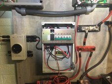
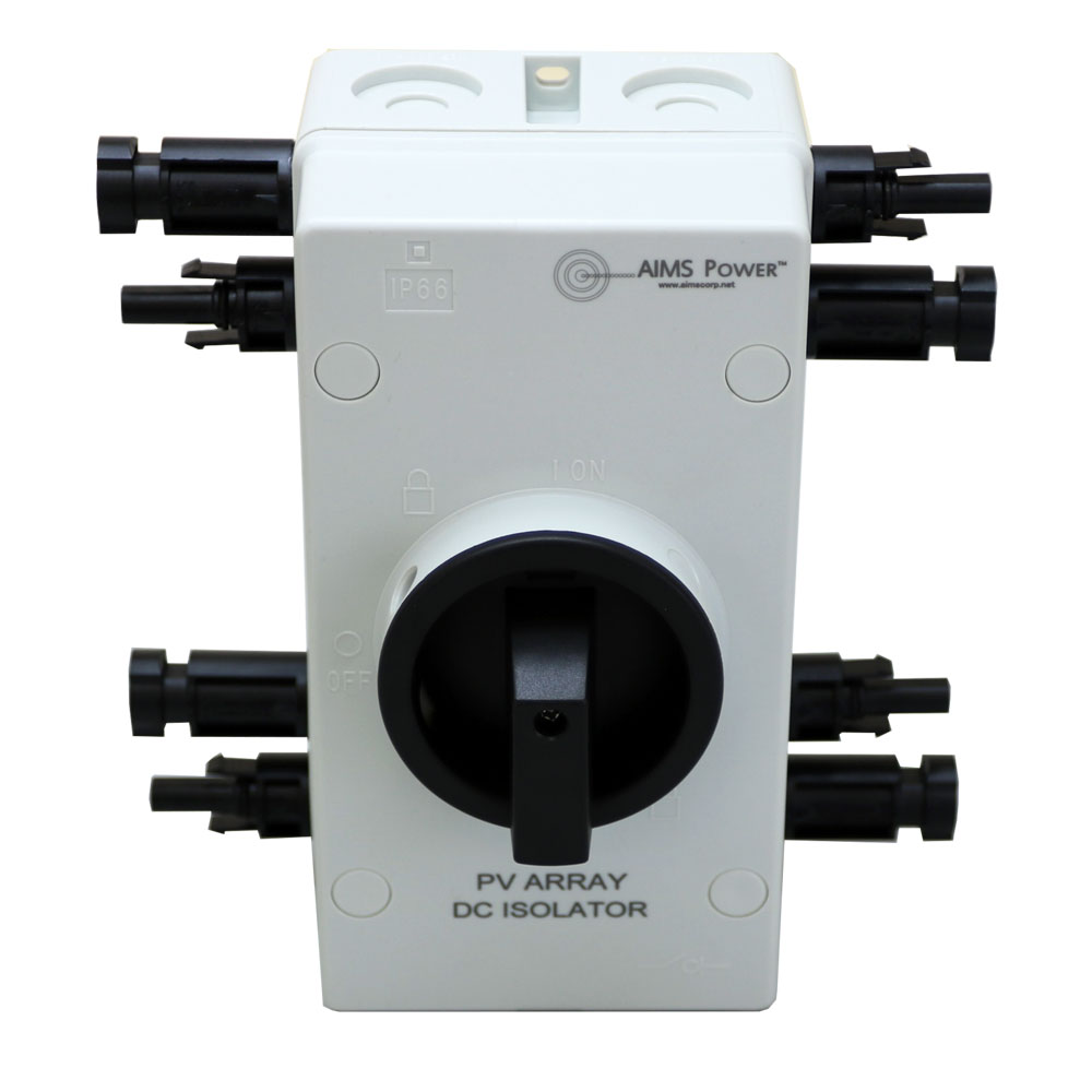
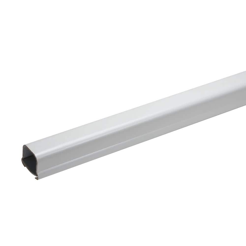
My inspector just came back to me and told me that any exposed portion of my DC wire must be in thin walled EMT. Based on my previous meeting I did not believe this was the case so now I have to change. Thought the plastic outside would be fine and no need in the garage.
I had dug a trench to bring the DC wire from my detached garage (where the panels are) to my home. That trench was approved. I used plastic conduit in the trench. Now, above ground and also along the joists and studs of the garage, the metal EMT has to be used.
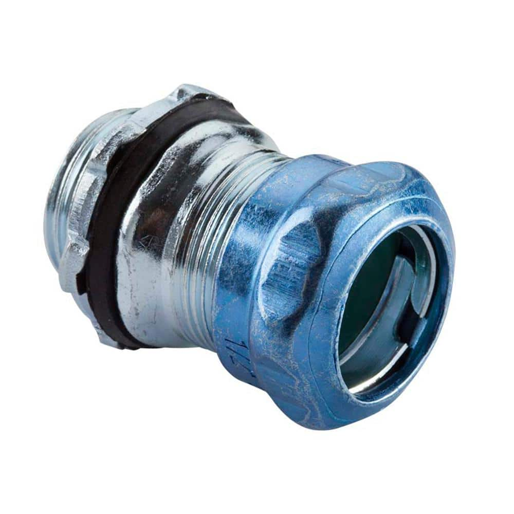
My question: How do I go about connecting non-rigid EMT from outdoors to the indoors? With the plastic this was easy and I just used the plastic conduit bodies and drilled a hole in the wall.
However, all the conduit bodies I see for EMT are either for dry location only or are threaded.
Any advice?
Thanks.
 

Help with Pvc to emt transition for DC PV wires entering dwelling​


Check out the above thread, it has good info.

 
Thank you so much!!! Had no idea I'd get this resolved so quickly. I know you have no idea who I am but after hearing back from the assessor, I was really discouraged that I had to do this (and also learn something new). Now I feel a lot better!

I'll get the EMT, one of the linked items above, and a threaded conduit body. And of course other connectors and a bender.

Thanks!!!
Pawn shops are great places to get benders with a bit of usage on them thatl be perfect for diy prijects.
 
Thank you so much!!! Had no idea I'd get this resolved so quickly. I know you have no idea who I am but after hearing back from the assessor, I was really discouraged that I had to do this (and also learn something new). Now I feel a lot better!

I'll get the EMT, one of the linked items above, and a threaded conduit body. And of course other connectors and a bender.

Thanks!!!
If you have never bent emt with a emt bender, buy a little extra EMT to practice with/learn with. There is definately an important technique to learn. Conduit bending becomes a math challenge also. There are small paper back guides/trade books with great info.
 
If you have never bent emt with a emt bender, buy a little extra EMT to practice with/learn with. There is definately an important technique to learn. Conduit bending becomes a math challenge also. There are small paper back guides/trade books with great info.
Agreed.
There are instructions to learn measurement points for bending measured bends.
Keep in mind to NEVER have more than 360degrees total of bends beyond a pull point. Or you will be sorry.
4 90’s or 8 45’s or some combination arranged.
 
Thank you so much!!! Had no idea I'd get this resolved so quickly. I know you have no idea who I am but after hearing back from the assessor, I was really discouraged that I had to do this (and also learn something new). Now I feel a lot better!

I'll get the EMT, one of the linked items above, and a threaded conduit body. And of course other connectors and a bender.

Thanks!!!
Download the bending app on your phone. I use Electrical Conduit Bender app on my droid. Works really well. Would have been nice years ago when I first started bending conduit for my new shop. Learned plenty then hands on. For videos to learn why you use an app, there is this playlist, does a great job explaining it. https://www.youtube.com/playlist?list=PLw8qsvCN6q_0WYifgt9fX2KHEeck8aJJD
 
Agreed.
There are instructions to learn measurement points for bending measured bends.
Keep in mind to NEVER have more than 360degrees total of bends beyond a pull point. Or you will be sorry.
4 90’s or 8 45’s or some combination arranged.
I prefer 180 degrees between pull points. Works out well for me. (Dont worry about small offsets bent in emt near pull points).
 
Thanks everyone for your help!

I have to wait until tomorrow to get the EMT rain tight connectors via shipping - no HD had it nearby.

In the meantime, I'm struggling with a couple other things. I realize that I can use the lb conduit bodies to connect from the outside to inside. However, I'm not sure what I use on the inside of the home and garage where the wire comes in.

In the picture I've attached you see the shut off for the PV on the bottom left. That's connected to the Morningstar Ground Fault device beside it, which has the connections to the LV6448. The LV6548 is currently connected via the plastic conduit to a sub panel.

For a bit of context, the pv wires coming into the left side of the PV shut off go to the left and then up to the rim joists where a hole was drilled through to allow the PV wires to come in. Right now the wires come in with no junction box attached to the rim joist. Just plain wire. I can take more pictures if that would help.

My inspector will want those wires in metal EMT. So I have to do an L shaped EMT and that has to attach to something on the rim joist. I was thinking just a regular metal junction box and connect the PV wires using MC4 connectors in the junction box. However I'm not sure if that's right and if so do I (in the junction box) just open up one of the holes on the backside and bring the PV wires through that (assuming that I'll use one of the attachments that take away the sharp edges of the junction box holes).

Also, what do I do when I get the EMT close to where the PV shut off is and the MC4 Connectors? Just leave an inch or two where the wire is not covered where the connections are made?

Hope this makes sense. Thanks again.
 

Attachments

  • morningstar ground fault.JPG
    morningstar ground fault.JPG
    620 KB · Views: 56
I thought NEC only requires metal conduit (FMC may solve a problem, somewhere, compared to EMT). There’s even a PV exception allowing down to MC. Can’t remember which code year that was.

EDIT: the FMC and MC advice are for dry locations. I’m not sure when you would be required to have metal conduit in wet locations for PV. Advisable, different story.
 
Last edited:
Also, what do I do when I get the EMT close to where the PV shut off is and the MC4 Connectors? Just leave an inch or two where the wire is not covered where the connections are made?

Not sure what exactly you are saying. But if it’s supposed to be in conduit and not just sleeved (my understanding is it is the former) you have to terminate the conduit in a box. And the box will have to be metal if it’s within the envelope where metal conduit is needed. If it’s outside you can pick and choose.

And note the EMT will have to be EGC bonded on at least one side.
 
You have the wrong PV box, that box is fine maybe at an array (although I have mine all in conduit at the array). This was mine when installing, notice the PV switches at far left side and how it was done. The botttom switch (not installed in this photo) required a bonding bushing for the metal conduit, one could use pvc and not need the bonding bushing.
EG4 mounting.jpg
 
You have the wrong PV box, that box is fine maybe at an array (although I have mine all in conduit at the array). This was mine when installing, notice the PV switches at far left side and how it was done. The botttom switch (not installed in this photo) required a bonding bushing for the metal conduit, one could use pvc and not need the bonding bushing.
View attachment 124859
nice conduit!

can do it! ?
 
Sorry for the confusion here. I hate not knowing the wording to describe what I'm doing.

My PV Box is a disconnect. Not just a junction box which it appears @Zwy is referring to. I think (correct me if I'm wrong) that you have one of those on the bottom left of your shelf.

With my disconnect box, it is hard to determine how I would get metal conduit to attach to it. I've attached a link to it here. It appears to have a few areas on the top that perhaps could be opened but I'm not even going to attempt that but may ask the company tomorrow.


I've seen how people have used metal raceway channel to hide wires and then the connections are just out of the channel at the very end. Raceway channel such as this:


At this point I don't know what to do. Perhaps I could talk with the inspector and see if he has some advice on what he'd accept although giving advice isn't really his job.

If you have any other suggestions (other than scrap the hole thing, lol), I greatly appreciate it.

Thank you.
 
Install the entire Disconnect switch inside a 12 x 12 x 6 NEMA1 J box. Cut out a round hole in the cover and mount the disconnect so only the rotary switch fits through the hole and is accessible while the body is inside. If the MC4 connector bodies can be removed from the cables then 3/4" EMT would work. Feed the wire into the J box then assemble the MC4 connectors. Leave sufficient wire so the MC4 connections to the disconnect can be made with the cover off then push the excess into the box and close (if hinged) or screw the cover on.
 
You would get higher quality help if you provide more pictures. The one you have is a little too narrow angle to figure out the situation. For instance, given that I only see 2 inches of the two devices at the top of the frame, I have to guess what they are. Probably the top left is a subpanel with regular 120/240V wiring. Top right is an inverter?

Also there's no schematic / text labels on the picture you provided. We have to expend extra mental energy figuring out how everything is connected, which is probably why you are getting very generic advice.

Might want to hit a reset button and think about this from a clean sheet. Also I'm concerned about your safety spider sense... those PV cables if connected in series enough are pretty high voltage! They should not be flopping around like that.

Disconnect - Don't go into this with PV wire / MC4, that's not a complete wiring system unless it's under your panels. Close up the punch outs for MC4 (if possible) and go into this with conduit. The PV can go in the conduits.

Those NM clamps you have around the individual PV conductors are for Romex, UF, and SE/SER cables. Not reusable in a proper install.

Inverter in top right? What model? I'm surprised it has exposed MC4 connectors instead of a wireway to which you can attach conduit.

Not sure if your inspector would be happy with exposed busbars for the 48V batteries I surmise are below the frame. I know you see these in a lot of YouTube videos. I think that's just for rapid reconfig and for educational purposes.
 
Back
Top