diy solar

diy solar

Failing System Analysing

doomsdaydevice

New Member
Joined
Feb 5, 2024
Messages
8
Location
Berlin
Hi,
I have designed my first small island system as an energy saving / blackout backup.
It consists of a solar input of minimum 300 W (3x100) extendable up to 600W (6x100) all 100 W with the same parameters
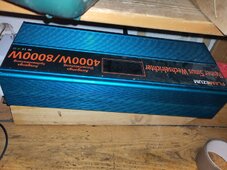
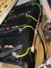
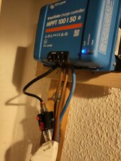
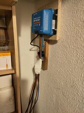
I connect them with a Victron MPPT 100 | 50 to a 12V / 400Ah LiFePo Battery Block, which powers a 12/220V inverter with 4000/8000W. The battery block consists of 4 12V100Ah batteries, each able to deliver 100/200Ah. The latter numbers (8000 and 200) are for the up to 5s peak.
So i think, batteries and inverter are harmonized.
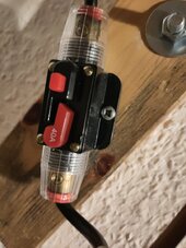
Between the charger and the batteries I placed a 40A circuit breaker, to protect it from currencies when a high load is requested from the batteries. The maximum that was requested every now and then is 3500W. The max load currency I observed was with 600W Solar connected around 35A.
The system worked quite well for around a year.
But lately my system showed problems when lots of sun is shining and the batteries had around 70% of load. For example:
- The victron charger detected totally different Voltage values. It switched far to fast between loading phases, to absorption, to float (when it just stopped charging) and once when it reached float it does not register, that the batteries are in use and can be charged again.
- The voltage curves sometimes "flip" around once a minute between 0V and 14V and the charger "makes noises"
- There are other strange observations i havend seen before and when the these strange observations start, I can disconnect the batteries and all solar inputs for a Moment, connect it again and then, for some time everythings switched back to normal, or lets say to what I would expect
When sun is shining, I can lately not connect the full capacity of 600W anymore. Then the problems appear quite fast. With 400W connected, the most common setup, it works mostly, but its winter, so hmmm
The questions I have
How can I ensure, that its the charger and not the batteries, which are broken?
Is it possible, that I fucked it up with a too high load on my batteries and that the 40A circuit breaker was an inappropriate protection for my poor victron charger :-( ?

Any other hints are welcome, I am quite Nooby in this field.

Thx and kind regards
 
Share your charge parameters, battery voltages (measured with a multi-meter preferably, cell voltages if available as well). 3.5kW at 12V is a lot of current - what cables are you using? Your charge controller can handle 50A to the battery, so that's fine.
 
Which 40A circuit breaker? The issue your describing exactly looks like the ones I would expect from a crappy cheap breaker.

Is it a genuine Bussman/Eaton/Bluesea or a cheap fake one?
And which wire length/size? On a 50A MPPT I would run 16mm2 wire

And which inverter? A REAL 4000W inverter is a expensive and heavy unit, and they are rare (for a reason, 12V is just not suitable for such power demands). Is it a proper brand pure sine wave?
My first guess this is also a cheap chinese one, which is more likely like 500W max..

Can you post some pictures?
 
Hi again
thx for the replies. The circuit breaker...hum, ya maybe its crappy, I dont know :oops:. I will add pictures. The 12=>220 inverter was rare, yes and not that cheap, so the question is, what is expensive? its a pure sinus (by self declaration 🤷‍♂️) and i can run all my devices until now without any issues. The cables from the charger to the circuit breaker has 10mm², but its just ca 15cm and then i doubled the cables to then either 2 times 10mm². The 16mm² cables were sold out when i was shopping for the project :rolleyes:. They were with 35A going through at most very light warm, even after longer periodes. Pure cooper cables. These double cables have the length between 1,5 to 2 m and go down to the busbar, where the batteries are connected to. The black double cable at the middle of the busbar on the picture of the battery block connects the power inverter. It were the cables delivered with the inverter so I assumed they are sufficient for the purpose.

I will share my measurement data as soon as i have my tools back. They are all in my Bus, its an oldtimer and in wintersleep a few 100km away, narf narf. At the moment I only have the data i can read from my victron and the data my inverter is showing.

And when I run some loads for some time and discharge the batteries to ~50% the inverster says battery voltage is e.g. 13.1 (which makes sense, when I disconnects any loads and the infeed). With nice sunshine the charger measures everything between 13.1 and 14.2 within one or two hours, not registering consumption and so battery discharge when once switched to float (in that case i have to disconnect it from solar and batteries to enforce a reboot, oh mann :confused: ).
While the charger values are really strange the inverter shows reasonable battery currencies (reasonable from what I would expect after my experiences from the one year of stable operation, and I was observing it a lot 😅)

I will deliver more data when available. Maybe that helps already. I can check for screenshots of my victron measurements, maye i have some from the wired periodes. Sometimes all is lost after a reboot...narf narf
 

Attachments

  • IMG_20240212_140722.jpg
    IMG_20240212_140722.jpg
    339.3 KB · Views: 20
  • IMG_20240212_140751.jpg
    IMG_20240212_140751.jpg
    159 KB · Views: 22
  • IMG_20240212_140816.jpg
    IMG_20240212_140816.jpg
    119.4 KB · Views: 22
  • IMG_20240212_140824.jpg
    IMG_20240212_140824.jpg
    120.1 KB · Views: 20
  • IMG_20240212_142626.jpg
    IMG_20240212_142626.jpg
    175 KB · Views: 21
Bin that breaker, thats one of the crappy ones. Replace with a proper fuse (And fuse near the batteries. There is no point of fusing the end of the wire).
For the wires, I would upgrade to 16mm2 especially on a 1.5-2m length. (With a fuse at the begin of the wire).

The inverter: Can't see the dimensions but I'm quite sure its not 4000W.. But based on the dimensions I think it should be able to power 600W.

But I would recommend using proper busbars and decent wires from the batteries. This looks like thin wires soldered to some copper water piping. I would remove that and rebuild using proper fuses, busbars, lugs and cables.
 
Ähm, what do you mean you cant see the dimensions of the inverter but you are quite sure? The dimension of the cable from the batteries (the busbar) to the inverter is 2 times 16mm² for both ways. And the dimensions of the inverter 4KW permanent, 8KW peak, pure sinus, thats how its written on it. And i am running my washing machine with it, sometimes with smaller consumers like fridge and / or notebooks in addition, and during consumption peaks it shows between 3KW and < 3.5KW, which is what I would expect and much higher then 600W.
Regarding the circuit breaker, I am with you, can replace it by a better one, if I find one, I searched and all I found seemed to be chinese, independent from the price, but its not necessarily bad I would say.
Why it does not make sense to put a fuse on any point of the cable way from the batteries to the device i want to protect from overloading, in that case the charger? Its more a practical thing, the rest of the cable way is hidden behind a locker.
The rest sound for me like recommendations for a system fine tuning (better cable diameter, better busbar) but it does not explain why my charger measures strange data, does not charge and needs reboots by complete disconnects.
I would assume either a problem with the charger or with the batteries, but if it would be the batteries i would expect same strange measurements at the inverter and at the charger. Which is not the case 🤷‍♂️
 
Last edited:
Your wiring from the batteries is no where near large enough to support a 3500 watt load.
The sticker says 4000 watts so we'll use that.
4000 watts / 12 volts = 333 amps
4000 watts / 10 volts = 400 amps (you should use this calculation as it's worst case)

The sticker on the unit means literally nothing. Cheap manufacturers can put anything they want on a sticker to sell more.

As recommended, check the breaker, it failing will cause exactly the symptoms you're experiencing. So would any other poor connection between the charge controller and batteries.
 
What are your charging parameters for the Victron 100|50?
Are you sure the batteries are getting fully charged?
I put the LiFePo program in the settings. And set the absorption voltage to 14.2. During the year of expected operation everything seemed OK and the batteries were fully charged every now and then. I do not have it 24/7 in operation.
I turn off the inverter, when below 13V battery voltage is measured. So there should be always 10 to 20% remaining load. And Full means 13.5V with no supply to the batteries, so in the night, and yes, every now and then i reached it
 
Your wiring from the batteries is no where near large enough to support a 3500 watt load.
The sticker says 4000 watts so we'll use that.
4000 watts / 12 volts = 333 amps
4000 watts / 10 volts = 400 amps (you should use this calculation as it's worst case)

The sticker on the unit means literally nothing. Cheap manufacturers can put anything they want on a sticker to sell more.

As recommended, check the breaker, it failing will cause exactly the symptoms you're experiencing. So would any other poor connection between the charge controller and batteries.
No where near large enough? Well, maybe its to small from diameter, which would mean I have some loss from the batteries to the inverter due to a resistance, or? And the cables would get warm in that case, or?
I know that the stickers can e a trick but i run the consumers i mentioned and my notebook / computers / hardware dont seem to trouble, which would be the case if not pure sinus and i run the heavy consumers and it works. So somehow it seems not that not large enough. But fair enough, even if here fine tuning would be possible, it does not explain my issues with my charger.
The circuit breaker / fuse is would be an explaination if it does not protect my charger from overloading it with too high currency on the consumer side and if it would not register a short cut current and disconnect. So I have to accept that I fucked up my charger because the disconnector (circuit breaker, fuse) did not disconnect 😭?
Any recommondations for a circuit breaker?
 
Regarding the wiring from Batteries / busbar to the inverter. I checked a table and its written for 1m 12V 200A (the highest value i found) 16mm² is not optimal, but also not critical. I have 1m from busbar to inverter, 12V and with some acceptable buffer at very most 400A and 2 times 16mm² for each direction, so at most 200A on each cable, much more likely in peak times between 160 and 170A.

And we are talking here about absolute peaks. In at least 98% (maybe 99.8%) of the time the inverter delivers < 1000W, in 80% <300W. I dont think my wiring is my main problem ;)

But if anybody has some table showing me that my data is wrong, pls post it here :)

Anyway Thx for now for all the answers :)
 
Last edited:
No where near large enough?
Yeah, Google an ampacity chart. To safely carry 400 amps with wire needs to be in the 100mm² ball park.
Well, maybe its to small from diameter, which would mean I have some loss from the batteries to the inverter due to a resistance, or? And the cables would get warm in that case, or?
Fire!
I know that the stickers can e a trick but i run the consumers i mentioned and my notebook / computers / hardware dont seem to trouble, which would be the case if not pure sinus and i run the heavy consumers and it works.
Computer, laptop chargers, etc don't constitute the 3500 watt load you mentioned earlier.
The 2*10mm² cables you have can safety run something in the 100 amp range.
So somehow it seems not that not large enough. But fair enough, even if here fine tuning would be possible, it does not explain my issues with my charger.
The circuit breaker / fuse is would be an explaination if it does not protect my charger from overloading it with too high currency on the consumer side and if it would not register a short cut current and disconnect. So I have to accept that I fucked up my charger because the disconnector (circuit breaker, fuse) did not disconnect 😭?
The charger is probably fine. Replace the breaker and retest.
Any recommondations for a circuit breaker?
Blue sea seems to be widely available and makes a quality product.
 
The system worked quite well for around a year.

Given this, i would not worry too much about the cables or inverter. It's easy enough to remove/replace the breaker to eliminate that.

Need to get some actual battery voltages to help figure out what is going on.
the batteries had around 70% of load

Are you saying 70% charge or the actual inverter load?
 
Given this, i would not worry too much about the cables or inverter. It's easy enough to remove/replace the breaker to eliminate that.

Need to get some actual battery voltages to help figure out what is going on.


Are you saying 70% charge or the actual inverter load?
Hi,
I was talking about 70% Battery load. The victron charger detects unreasonable voltage values. And the problem gets worse. Newest example:
I reduced the load of the battery (by consuming) to at most 30% (13.0V lt. battery manual). Sun was shining little the next day, max. Power from solar measured 440W, harvested in sum 430Wh, the charger detected the batteries are full, it went via absorption to float and stayed in float till i came in the evening when it was dark. It did not even recognize that its dark outside 😥. I had to reboot it (disconnect all energy sources) and then after reconnect it registered 13.1V from the battery block, same value the inverter measured as current battery voltage and reasonable from what was in the batteries and what was charged. For me it seems that the charger runs into a problem when the power exceeds a certain limit, which should be in its limits and then it goes crazy until it gets a reboot.
Its for me still hard to believe that its the circuit breaker but I would love if you all are right and i am wrong and i will test it immediately after my holidays :). Its for sure not a good one and i will replace it. But I fear then its still the charger. If it would be the batteries, the inverter would read same crappy data the charger reads.
Naja, lets see. Before I leave my flat I will reduce the solar power to 200W, that it charges continously with a small power to not stress whats left from the device. there will be no consumption anyway.

Thx for your answer 🖖
 
For me it seems that the charger runs into a problem when the power exceeds a certain limit, which should be in its limits
Replace the breaker connected to the controller. Replace with a 60 amp fuse as recomended. The type of breaker you have used are very unreliable, and can cause intermittent volt drops and/or disconnection. Note this fuse should be positioned near the battery positive buss bar, this provides protection for the cable to the controller and the controller itself, from excessive battery energy, if a fault occurs in the cable or controller.
Cables to the inverter, 2 x 16mm2 has a maxinum safe rating of 220 amps, for operating the inverter at 3000 watts you need 50mm2, minimum, cable protected by a 300 amp fuse, fuse as close to positive buss bar as possible.
Ideally replace the copper pipe buss bar with quality items rated for 300 amps. Replace battery terminal to buss bar cables with 16mm2 cable.
Note in a battery powered system fuses or quality breakers are positioned as close as practical to the battery bank or battery positive buss bar.
 
Hi all

Blue Sea Circuit Breaker is installed and my system works like a charm again already for several days 🤩
. With as much power as possible. So even if I still do not understand, why my charger measured such strange values, it stopped and behaves exactly as expected. You were all right.

Thx a lot 🖖🙃
 
Back
Top