diy solar

diy solar

Feedback on adding 2 panels to my RV solar array

culty

New Member
Joined
Jul 13, 2023
Messages
49
Location
USA
EDIT: Updated plan design here (further down in this thread).

I should have 2 additional 395w panels to add to my solar array in the next week or two. My plan is to add the Renogy Rover 30A MPPT charge controller to handle the two additional panels, since the Growatt 3000 24v can only handle 150v max input. My understanding is that I can run them directly into the 24v bank which the Growatt is connected to.

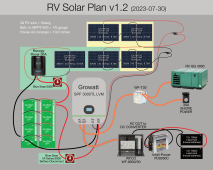
Below is my current working system design (grey) + the planned add-on (green). The panels are on their way, but the Renogy isn't locked in yet. I'd love any and all feedback on the plan, as well as any other potential issues I need to consider, or elements which will make this more rock-solid.

Thanks!

IMG_1590.png
 
Last edited:
Since you didn't link a manual, I used this one:


The renogy lists 100V max Voc. You show them in series, so your 41Vmp panels are likely very close to 50Voc meaning that if it ever gets below 77°F, you'll over volt your controller. If you put them in parallel, you would be fine.

Your 3S configuration on the Growatt is also at risk of overvolting the MPPT.

Generally speaking when matching panels to mppt, you need a ~15% margin on your Voc to insure cold temperatures do not overvolt the MPPT.
Thanks @sunshine_eggo! Here's the spec sheet on my panels:


The upper left most chart on page 2 (third column from the right) indicate that my panels have an open circuit (Voc) of 49.03 and a max voltage of 40.73 under load. I thought these were absolute top end for the panels in ideal conditions. Is that not the case? My goal is to keep amperage is low as possible for wiring size and length.

If my assumption is incorrect, would it be best to install some in-line fuses rated at some number close to (but below) 150V?

Also, I assumed that reaching peak (or above) voltage under load was fairly unlikely given that my panels are flat mounted; when the sun is most likely to be nearly perpendicular to them (summer solstice), the temps will be fairly high on the panels due to summer heat. But if that's not a prudent assumption, I would much rather know now than after turning the Growatt into an oversized paperweight. ?

Depending on your answers, I will look into reconfiguring my plan for the two additional panels in parallel strings, or size up the Rover.
 
Thanks @sunshine_eggo! Here's the spec sheet on my panels:


The upper left most chart on page 2 (third column from the right) indicate that my panels have an open circuit (Voc) of 49.03 and a max voltage of 40.73 under load. I thought these were absolute top end for the panels in ideal conditions. Is that not the case?

No. STC ratings are for STC:

1690668517783.png
Higher temps give lower voltage.
Lower temps give higher voltage.

1690668996530.png

Voc temp coeff: For every °C above 25, your voltage decreases 0.3%. For every °C below 25, your voltage increases 0.3%.

You ALWAYS size the Voc to allow for cold temperature effects. This depends on your climate. In most cases about 15% margin is needed, thus you would not want your Voc to exceed about 128V.

My goal is to keep amperage is low as possible for wiring size and length.

Goals for their own sake are typically not meaningful and may be detrimental. This is an arithmetic exercise. Each configuration has its own outcome.

Given that this appears to be for an RV, you're actually doing the opposite of what most would. More parallel on a flat roof with shading potential is better.

A properly configured array may increase your voltage drop, and you might lose a few % of efficiency, but you won't pop your MPPT. Your goal is encouraging you to destroy your equipment.

If my assumption is incorrect, would it be best to install some in-line fuses rated at some number close to (but below) 150V?

This isn't a thing, and I don't think you understand what you are suggesting. You can't protect against voltage, only amps.

If you ever get below about 70°F, you run the risk of blowing your MPPT... "letting the magic smoke out" stuff.


Also, I assumed that reaching peak (or above) voltage under load was fairly unlikely given that my panels are flat mounted; when the sun is most likely to be nearly perpendicular to them (summer solstice), the temps will be fairly high on the panels due to summer heat. But if that's not a prudent assumption, I would much rather know now than after turning the Growatt into an oversized paperweight. ?

Load doesn't matter.

Light gives volts
Intensity of light gives amps.

Ambient light just before sunrise can produce near full rated Voc.

You are trying to argue against an entire industry. You need to go 2S2P on the Growatt and 1 panel on the Renogy.

Depending on your answers, I will look into reconfiguring my plan for the two additional panels in parallel strings, or size up the Rover.

There is no need to size up the Rover. Just stick with one panel.
 
you need to get a mppt that can handle 150v. Your battery is 48v - so you can’t put the two new panels in parallel.

With a Voc of 49.3 times 2 = 98.6v - you will blow up a 100v mppt very quickly.

I don’t know the Renogy products… if you were using Victron I would recommend a SmartSolar mppt 150/35.

—-

Actually- because you are at risk of quickly blowing up the mppt in your GroWatt (it is 150v -right?). You should have two panels (2s) going into it, and then three panels going into the mppt - but you will need a 200v+ mppt for that.

Here is my best idea - if the Growatt can handle it:
put four panels into the Growatt on a 2s2p configuration (input 82v and19,56a - can it handle that???) and then have the 5th panel go into the 12v house batteries with the Renogy Rover - this will be slightly over paneled- but with the flat mount you will very seldom see clipping.

That should solve both problems of having too much voltage for the Growatt and the mppt. You could also install a switch to cut the intellapower charger and just let the solar panel keep the battery charged - if it isn’t enough because of clouds,etc, flip the switch for a bit to charge into the house battery.

Both Sunshine-eggo and I are trying to prevent your equipment from dying due to over voltage.

If you have any other questions- please ask.

Good Luck
 
Last edited:
I was just looking at the specs for the GroWatt.

Max Voc 145v- danger you are over this.
Pv voltage 30-115vdc
Max PV input -4500w
(So it can handle about 39 amps of Pv input)

So - go 2s2p of panels into the Growatt!
Then decide what to do with the 5th panel.
Options:
get one more and go 2s3p into the growatt.
Or put the 5th panel into the 12v house battery.

The standard 10awg Pv wires will handle 30amps (that’s what they are rated at). So 20amps through them will be no problem.

If you decide to go 2s3p of panels- from the Pv combiner to the Growatt go with 8awg wires.

On your drawing I don’t see fuses, breakers, or switches. From the panels to the Growatt/mppt you need a switch/breaker so you can “turn the sun off”. You also need a fuse (class T preferably) just after the battery and a switch (so you can do maintenance on the Growatt).

Label the wires with the size of wires that way we can see if a wire is under or oversized.

You may also want a shunt based battery monitor - that way you can know how full the lithium batteries are (and maybe one on the 12v house bank too). I love my Victron Smartshunt. I know exactly what charge level the batteries are at - helps me know if I should run the generator- or not.

Your lithium bank says 48v and 80ah (8times 24v20ah in 2s4p) - what batteries are those? With that arraignment you will need to verify they are staying in sync. Do you have Bluetooth for those batteries? Or will it be a manual process?

Good Luck
 
No. STC ratings are for STC:

View attachment 160058
Higher temps give lower voltage.
Lower temps give higher voltage.

View attachment 160063

Voc temp coeff: For every °C above 25, your voltage decreases 0.3%. For every °C below 25, your voltage increases 0.3%.

You ALWAYS size the Voc to allow for cold temperature effects. This depends on your climate. In most cases about 15% margin is needed, thus you would not want your Voc to exceed about 128V.
Thanks @sunshine_eggo! This is all VERY helpful information! I am very new to all of this, and feel a bit like I'm drinking from a fire hose. I really appreciate you and @Rocketman taking the time to addressing the flaws in my thinking as well as my system. I'm still learning much of the lingo, and just did a deep dive on STC. Indeed, I was misreading/misunderstanding what that chart was implying. Your corrections helped point me in the right direction.

Goals for their own sake are typically not meaningful and may be detrimental. This is an arithmetic exercise. Each configuration has its own outcome.

Given that this appears to be for an RV, you're actually doing the opposite of what most would. More parallel on a flat roof with shading potential is better.

A properly configured array may increase your voltage drop, and you might lose a few % of efficiency, but you won't pop your MPPT. Your goal is encouraging you to destroy your equipment.
You make some sound points here. And you're right, my goals will undergo some refinement re: your suggestions!

This isn't a thing, and I don't think you understand what you are suggesting. You can't protect against voltage, only amps.

If you ever get below about 70°F, you run the risk of blowing your MPPT... "letting the magic smoke out" stuff.
Yikes! I think I grasp your point, and now have a better understanding of why. Noted!

Load doesn't matter.

Light gives volts
Intensity of light gives amps.

Ambient light just before sunrise can produce near full rated Voc.
Good to know, and crazy! I'm still trying to grasp the "pipe vs water flow" analogy for volts vs. amps. Light vs. intensity is yet another layer I get to learn about ?

You are trying to argue against an entire industry. You need to go 2S2P on the Growatt and 1 panel on the Renogy.
I apologize if my responses/clarifications sounded like argument. That was not my intention. It wouldn't be the first time in my life that's happened, so I can comfortably say it's not you, it's me. It's a work in progress ?. That said, I want to re-iterate that your comments and follow ups have been invaluable. Thank you.

There is no need to size up the Rover. Just stick with one panel.
Got it. Thanks!
 
Both Sunshine-eggo and I are trying to prevent your equipment from dying due to over voltage.

If you have any other questions- please ask.

Good Luck
Hugely appreciate both of your experience and brains. Thank you!

I was just looking at the specs for the GroWatt.

Max Voc 145v- danger you are over this.
Pv voltage 30-115vdc
Max PV input -4500w
(So it can handle about 39 amps of Pv input)
I see on page 43 of my Growatt model's manual (24v version) that it is rated for 80a PV input. But if I'm misunderstanding something, please definitely correct me.

So - go 2s2p of panels into the Growatt!
Then decide what to do with the 5th panel.
This is a much more sound plan over the one I had at the beginning of this post.
Options:
get one more and go 2s3p into the growatt.
Or put the 5th panel into the 12v house battery.
A friend said I could run both sets of panels through their own respective charge controllers, and then have them each charging the single battery bank (currently the LiFePO4 24v nominal bank comprised of 8 24v20ah batteries all in parallel = 24v160ah bank). Is this a sound approach having two different charge controllers running into a single battery bank? The cells in each battery are 1C, with 3C max charge rate. Each battery is composed of 16 cells (8s2p) with a BMS in each. I'm not entirely sure what the BMS is rated for, but I can find out if it's necessary to know.

The standard 10awg Pv wires will handle 30amps (that’s what they are rated at). So 20amps through them will be no problem.
Cool.

If you decide to go 2s3p of panels- from the Pv combiner to the Growatt go with 8awg wires.
I don't think there's room to have 6 of these panels on my roof and have easy roof access; I also have 5 currently, so I'd have to match one last panel, which might be tricky. So the plan was to stick with 5.

On your drawing I don’t see fuses, breakers, or switches. From the panels to the Growatt/mppt you need a switch/breaker so you can “turn the sun off”. You also need a fuse (class T preferably) just after the battery and a switch (so you can do maintenance on the Growatt).
I just received this Blue Sea 6006 battery disconnect switch which I intended to install between the battery and the Growatt. I have been researching 2-pole disconnects as well, but have yet to find one I feel good about. Same with fuses. If you have recommendations, I'd love some options to consider!

Label the wires with the size of wires that way we can see if a wire is under or oversized.
Great suggestion! I'll do this and update the image!
You may also want a shunt based battery monitor - that way you can know how full the lithium batteries are (and maybe one on the 12v house bank too). I love my Victron Smartshunt. I know exactly what charge level the batteries are at - helps me know if I should run the generator- or not.

Your lithium bank says 48v and 80ah (8times 24v20ah in 2s4p) - what batteries are those? With that arraignment you will need to verify they are staying in sync. Do you have Bluetooth for those batteries? Or will it be a manual process?


Good Luck
I've been looking into a shunt as well, and likely will add one soon. I'm starting to see I've one things way out of order. That said, I'm really happy to have power on board, but I definitely have pieces to make this smart and safe. I was dealing with generator CO ingress into the cabin, so I felt highly motivated to get alternate remote power working. This is meant to be an initial build that I am in the process of beefing up.

For instance, I'll probably be reconfiguring the cells from their current 8s2p configuration to something like a few batteries in an 8s16p configuration. Since these are lightly used batteries, I'm testing all of my cells (headway 3.2v 10ah). Many of them are testing above their rated power, so they're essentially brand new. I'll likely be making a few grades of them (e.g. Grade A, B, and C), then organize uniform cells into a few larger 24v batteries with BMS (including active balancing).

Again, I appreciate your questions, suggestions, and corrections. I'll update the drawing with the additional details and modified plan. Any other feedback you have, I'll definitely soak it up!
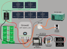
 
I've gotten some really constructive feedback in this thread so far. Attached is my updated plan design updated with suggestions/feedback proposed in this thread. Green BG is new elements being added, and yellow is the modified panel configuration (from 3 panels all in series to 4 panels in 2p2s configuration).

The known pieces still missing/unresolved are:
1. fuses/breakers;
2. I'm unsure whether my friend's recommendation of running 2 separate MPPT controllers into the same battery bank (as outlined below) is acceptable.

Did I miss anything? Is there anything else warranting criticism here? Thanks for the great input!

IMG_1601.png
 
You can run as many mppt’s into a battery bank as you would like. Our friends in the sailing world will often have one mppt per panel - so if they have 7 panels they have 7 mppt’s. They deal with LOTS of shading issues (masts,lines,etc) and need all the power they can get.

I missed where you said the system was 24v- I looked at the way you labeled your batteries and thought 48v system.(to me it looked like two 24v batteries in series). But no problems.

The bluesea switch going from the Rover to the batteries you may want to consider changing to a Dc breaker. (You probably need a fuse or breaker on that line - so go with a good breaker and eliminate that switch).

I still think that it might be a very good idea to move the rover to the 12v house bank (or might not be). You have two devices to convert and charge the 12v batteries. You want to find out how much watts each uses 24/7 and what the efficiency levels are, then compare that with moving the Rover to the 12v batteries.

My guess is your 24v array will be in float quite a bit, so moving the Rover to the 12v batteries will reduce your overall load and be more efficient. Especially if you put in a switch so you can turn off the WFCO and Intel’s-Power until they are needed. The 395w may (or may not) completely power your 12v side on good days.

The nice thing is you can set your system up with the Rover going to one bank - test it, then move the Rover to the other bank and test it and see which you like better.
 
I just had another thought… have you already purchased the WFCO and Ineli-Power?

If not consider a Dc-Dc charger 24v-12v - Victron makes one - I am sure there are others too.
Also, Any loads going out of the lithium bank should have a low voltage cutoff- your GroWatt does, if you put a Dc-Dc charger (or any other 24v loads consider running them through a Victron Smart Battery Protect (BP65). This will stop the draining of the battery at a certain voltage then restart when a set voltage is obtained (both user setable). I used these on my MotorHome so the loads can never shutdown the bms- that way the bms is available for the morning when solar hits the panels.

Good Luck
 
You can run as many mppt’s into a battery bank as you would like. Our friends in the sailing world will often have one mppt per panel - so if they have 7 panels they have 7 mppt’s. They deal with LOTS of shading issues (masts,lines,etc) and need all the power they can get.
Thanks Rocketman. Are there any considerations re: max potential combined amperage when running multiple controllers to one bank? The cells are 1C (10a) standard, but can charge as high as 3C I believe. But I'm assuming the BMS on each battery would handle charge current anyway, and limit current based on its own set values. But I want to check that my assumptions are correct so I can keep everything happy.

The bluesea switch going from the Rover to the batteries you may want to consider changing to a Dc breaker. (You probably need a fuse or breaker on that line - so go with a good breaker and eliminate that switch).
I plan on putting some fuses in line before the disconnect switch on the batteries as well as fuses/disconnect on panels.

As far as breakers go, I'm still uncertain how to feel about them. I see some people saying hell yeah to them, and others saying DC breakers are unreliable and prone to failure in DC/solar applications. From this, I've understood that reliably breaking DC circuits is much more tricky than AC applications. I've also heard rotating disconnects are safer than switches, because they reduce/eliminate the chance for arcing. I haven't done a deep dive yet since I've had plenty of other elements to figure out, but I would love a more definitive understanding of what breakers (if any) are safe and dependable (if you or anyone else has reliable information on the matter).

I still think that it might be a very good idea to move the rover to the 12v house bank (or might not be). You have two devices to convert and charge the 12v batteries. You want to find out how much watts each uses 24/7 and what the efficiency levels are, then compare that with moving the Rover to the 12v batteries.

My guess is your 24v array will be in float quite a bit, so moving the Rover to the 12v batteries will reduce your overall load and be more efficient. Especially if you put in a switch so you can turn off the WFCO and Intel’s-Power until they are needed. The 395w may (or may not) completely power your 12v side on good days.

The nice thing is you can set your system up with the Rover going to one bank - test it, then move the Rover to the other bank and test it and see which you like better.
I think this is a good idea to test and compare. Also a 24v to 12v converter might be the way to go (and eliminate the inteli-power). In answer to your question in your last follow-up post, the WFCO and Inteli-Power came with RV when I purchased it, so it's been nice to have the plug and play option while I get my initial system installed and working. I imagine (depending on energy usage) I will want to optimize/replace components for efficiency.

And finally, when it comes to panels feeding the 24v bank, there are a few reasons my current plan is to take all solar to the one bank:

1) The batteries in my current setup were acquired were from a company that had failed them in their QC tests. But the BMS didn't have active balancers, so a lot of the cells are in like-new condition. My current bank is a temporary 4kWh placeholder made of 8 of the highest-rated batteries from this batch. Whatever I build next (probably a few ~4kWh batteries in an 8s16p configuration, or something similar) will be constructed from the individual cells. I'm almost halfway through the process of testing all cells in these batteries (I have 320 3.2v/10ah cells total).

2) Even though I plan to have something between 8kWh-16kWh storage in my final setup, I would love to have enough solar to run high-draw components with minimal dependence on batteries (yes, I'm looking at you Air Conditioner and Fridge). I also have some tools and electronics on board when I travel that will depend on AC power, so the losses I get to the DC side are a somewhat temporary tradeoff I've made with the plan to eliminate them (or at least reduce the need to care about them once I have enough storage).

3) Finally, I don't know if it's reasonable to replace the LA batteries under the step, but I kind of love the idea of building some custom drop-in replacements for them so I am all LiFePO4 on board. ?
 
Just scanning your system makes me wonder if your 2 panels will be too much battery charging current for the 30A Rover. Remember it’s not panel current rather battery charge current that is the rating.
 
Just scanning your system makes me wonder if your 2 panels will be too much battery charging current for the 30A Rover. Remember it’s not panel current rather battery charge current that is the rating.

Deleted cuz I didn’t read well and thought OP only had a 12v system.
 
Don’t assume the bms will limit the charge amps into the batteries. (I don’t think they will - they will just stop charging into that battery if the voltage goes too high). You may need to set the Growatt so it doesn’t overcharge the batteries. Calculate all charging sources for this. For right now it may be better to just have one battery charge source (Growatt) instead of two- while your battery is small. Don’t force too much power into cells. (Growatt + Rover). I think a .3C is what is recommended to charge lithiums. 160ah *.3 = 48amps.
 
Don’t assume the bms will limit the charge amps into the batteries. (I don’t think they will - they will just stop charging into that battery if the voltage goes too high). You may need to set the Growatt so it doesn’t overcharge the batteries. Calculate all charging sources for this. For right now it may be better to just have one battery charge source (Growatt) instead of two- while your battery is small. Don’t force too much power into cells. (Growatt + Rover). I think a .3C is what is recommended to charge lithiums. 160ah *.3 = 48amps.

Here's the data on the individual Headway 38120S cells in my batteries. It lists recommended charge current at 1C (10a), and max charge current at 2C. I was mistaken that max is 3C — that's for discharge.
 
Thanks Rocketman. Are there any considerations re: max potential combined amperage when running multiple controllers to one bank? The cells are 1C (10a) standard, but can charge as high as 3C I believe. But I'm assuming the BMS on each battery would handle charge current anyway, and limit current based on its own set values. But I want to check that my assumptions are correct so I can keep everything happy.

Per @Rocketman, BMS don't limit current. They cut it off, i.e., if the BMS is rated for 100A and the load on the battery exceeds 100A, the BMS will cut off the load to 0A not limit it to 100A.

BMS are simply charge/discharge on/off switches with various rules for when those switches can be on or off.
 
Back
Top