I wanted to make a stand-alone home backup unit that was modular and small enough to move easily— but robust enough for sustained power tool use and 2+ days of emergency lighting and refrigeration. Stretch goal: an attractive form factor that doesn’t involve a hand truck.
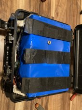
To keep the build simple, I rolled the dice on a battery pack by Mr. Li via AliExpress. Amazingly, the unit arrived in about 2 weeks even w/ free shipping, and so far it has tested true to spec.
-Battery: 2.4kw/24v 8s1p 100ah prismatic lifepo4 w/ built-in BMS (I plan to build from raw cells next time)
-Inverter: 2500w/5000 surge single phase by CNSPower/Xijia
-Charge controller: Epever Tracer MPPT 40amp w/ MT-50
-AILI battery monitor - 150 amp
-2x 24v USB QC 3.0 ports w/ volt meter (bypasses inverter)
-2x USB 2.4 ports (run off AC outlets)
-4x 120v AC outlets protected by GFCI
-Protections: 200amp main breaker; 50amp breaker to charge controller; 15 amp fuse to USB 3.0; multiple on-board protections for the BMS, inverter, and MPPT
-SAE port for mobile solar array (coming soon); will charge fully in 1 day on 4x100w - I plan to add wind capability at some point. No grid input. Ever.
-Lightning bolt flair painted by 8 y/o helper
My total system cost was around $1600, and Will’s videos/links/book and this community were hugely helpful! This medium suitcase-sized box runs cool and quiet with plenty of room to expand, and it’s nice to be able to point things out through the acrylic door to help our kids learn. Happy so far!
Questions or suggestions or want component detail/links — please let me know!