diy solar

diy solar

Flexible bus bar question

But in the end, the flat copper bar/pipe isn't really completely flat at the surface, is it? Does it still work fine for you?

I tried braid with round lugs, but you have to roll up the braid, which makes it more stiff. With flat braid, you can go up, with these (see below), the bend has to go to the side, as the distance between the terminals is too little, to have the rolled up braid go up. The lugs have quite sleeve for cable/braid, this takes up too much space to go straight between terminals.

1629121121979.png
 
But in the end, the flat copper bar/pipe isn't really completely flat at the surface, is it? Does it still work fine for you?

I tried braid with round lugs, but you have to roll up the braid, which makes it quite stiff again. :-(
It works fine up to my maximum system current draw, which is 200 amps. You could polish the fine marks out if that is concerning.
 
See the pictures I posted. I am only using the braided bus bar for one connection that I couldn't make work with flat copper bar. For my batteries, I'm using tin-plated copper bus bar that a forum member made for me in a group buy.
 
See the pictures I posted. I am only using the braided bus bar for one connection that I couldn't make work with flat copper bar. For my batteries, I'm using tin-plated copper bus bar that a forum member made for me in a group buy.
OK, thanks.
 
You're welcome. I got lucky with my timing and was able to purchase some fantastic bus bars from a forum member. He tried to do a second, larger group buy but there wasn't enough interest ?‍♂️ I don't yet have enough experience to give you other ideas.
 
You're welcome. I got lucky with my timing and was able to purchase some fantastic bus bars from a forum member. He tried to do a second, larger group buy but there wasn't enough interest ?‍♂️ I don't yet have enough experience to give you other ideas.
That was LtDan. I bought some from him also. Very nice quality
 
K8MEJ:
Like you, I wanted flexible cell interconnects. I wanted them to allow for spring-compressed cell expansion. i prefer to only use tinned copper, so the rather costly, and only slightly flexible, non-tinned CALB bus bars don’t interest me. Looking at tinned copper braid, I found that high ampacity braid is pretty expensive.

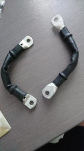
I ended up making my own out of 5-inches of #1 AWG TEMCO welding cable ($1 for 5” from Amazon in the form of a 15-foot length) and tinned copper SELTERM terminal lugs ($1 each from Amazon in qty 25.) I already owned a hydraulic crimper (a cheap Chinese version that works quite well), so the cost was $3 per interconnect. And I know the ampacity for sure.

If you are going to make your own out of flexible copper braid, be sure you know the ampacity of the braid. If the ampacity of the braid isn’t listed, you can be sure that it is pretty low. Even then, try to verify by asking how many strands of what gauge wire are used to construct it, and confirm the calculation.

Here is a photo of one of my DIY flexible interconnects. (The photo was taken before adding a bit of shrink tubing to cover the crimped end of each lug.) The ampacity of this #1 AWG wire is almost exactly the same as the rigid bus bars that came with my 280:amp cells, although they are obviously a bit longer.

I found that bending the cable after stripping the ends, and before crimping the lugs, produces an interconnect that pretty well holds that shape, while being pretty flexible over a limited range of motion.

Kind regards,
John, K7KEY
John,

How are your flexible 1 awg cables to connect battery cells holding up? How many amps are you running through them regularly and at maximum.
I made some similar cables purchasing the flexible welding cable from TEMCO 1awg rated at 240amps using their ampacity chart. They tested well at low amps but I haven't tested them at higher amperage. My initial assumption was that the flexible fine stranded welding cable could handle higher amperage (also using the TEMCOs ampacity chart) but further research has me beginning to believe that I my assumption may have been inaccurate and that TEMCOs ampacity chart is for momentary like welding rather than continuous and what really matters is the cross section width of the cable. Anyway...long story I short I've already made the cables and used them for small loads while testing batteries but not for higher loads. My battery build is 24v 8s and will be using JBD 150bms and a 3000watt inverter rarely if ever at max so trying to figure out if they would still be safe to use or not and what your experience was?


I am still curious about your experience but as a quick follow up, I called TEMCO explained to me that my thinking was incorrect and that ampacity charts can vary by manufacturer and that their chart shows the ampacity for any use including battery cables.
 
Last edited:
My cell interconnect “cables” are very easily flexible enough to accommodate any movement of the cells in response to expansion or contraction during charge or discharge, which is small movement, if any at all. (I have the battery cells clamped under spring tension). I was just not comfortable with rigid bus bars for this reason.

As far as ampacity, I have three 24-volt, 280-amp-hour, lithium batteries in parallel. I never charge/discharge at more than 180 amps total, and rarely than much. My usual maximum charge current is 130 amps into the three parallel batteries. My discharge rate rarely exceeds 100 amps, so I don’t even come close to testing the current capacity limits of the 1/0 “flexible bus bars”. I am happy to have everything coasting gently along. Sorry, but I don’t have any experience at pushing them hard.

There really is no such thing as the exact, one true, ampacity of a cable. It depends upon the voltage drop you can tolerate, and/or the amount of energy waste you can tolerate, and/or how hot you can tolerate for the cable insulation to get.

Any standard 1 AWG wire (copper) has a resistance of about .013 ohms per 100 feet of length. In my 24-volt battery I have seven of these 1 AWG “flexible bus bars” that are 5 inches long each, or 35 inches in total. Rounding, this means that if 100 amps are pushed in or out of the battery, these seven “flexible bus bars” together will drop approximately (3/100 x .013 ohms X 100 amps) = .04 volts. The amount of power wasted will be (.04 volts x 100 amps) = 4 watts. Is that acceptable? If you draw 200 amps, the seven “flexible bus bars” together will drop .08 volts, and waste 16 watts of power. Is that acceptable? You decide.

NEC wire ampacity charts are based upon the maximum current that will result in heating of the wire that does not exceed temperature rating of the insulation, and no more than 10 percent voltage drop over the total wire length (out and back distance). This is usually for wiring in buildings. NEC ampacity charts are not very relevant for battery interconnects. This is why there is no definitive single ampacity number for welding/battery cables.
 
Last edited:
My cell interconnect “cables” are very easily flexible enough to provide accommodate any movement of the cells in response to expansion or contraction during charge or discharge, which is small movement, if any at all. (I have the battery cells clamped under spring tension). I was just not comfortable with rigid bus bars for this reason.

As far as ampacity, I have three 24-volt, 280-amp-hour, lithium batteries in parallel. I never charge/discharge at more than 180 amps total, and rarely than much. My usual maximum charge current is 130 amps into the three parallel batteries. My discharge rate rarely exceeds 100 amps, so I don’t even come close to testing the current capacity limits of the 1/0 “flexible bus bars”. I am happy to have everything coasting gently along. Sorry, but I don’t have any experience at pushing them hard.

There really is no such thing as the exact, one true, ampacity of a cable. It depends upon the voltage drop you can tolerate, and/or the amount of energy waste you can tolerate, and/or how hot you can tolerate for the cable insulation to get.

Any standard 1 AWG wire (copper) has a resistance of about .013 ohms per 100 feet of length. In my 24-volt battery I have seven of these 1 AWG “flexible bus bars” that are 5 inches long each, or 35 inches in total. Rounding, this means that if 100 amps are pushed in or out of the battery, these seven “flexible bus bars” together will drop approximately (3/100 x .013 ohms X 100 amps) = .04 volts. The amount of power wasted will be (.04 volts x 100 amps) = 4 watts. Is that acceptable? If you draw 200 amps, the seven “flexible bus bars” together will drop .08 volts, and waste 16 watts of power. Is that acceptable? You decide.

NEC wire ampacity charts are based upon the maximum current that will result in heating of the wire that does not exceed temperature rating of the insulation, and no more than 10 percent voltage drop over the total wire length (out and back distance). This is usually for wiring in buildings. NEC ampacity charts are not very relevant for battery interconnects. This is why there is no definitive single ampacity number for welding/battery cables.
Thanks for thoughtful reply. I can definitely tolerate the voltage drop /loss of power. My inverter is 3000 watts and my bms is rated for 150 continuous amps but I highly doubt I will max either out, rarely if ever. My main goal is to keep things safe so my main concern would be round heat generated so I guess its prob with testing once its all set up at max load and upgrading the wire if it gets to hot. I would just hate to spend all the money on making new interconnects unless its needed.


I forgot that I had previously purchased some braided copper ground straps rated for 150amp (100 - 120amps continuous) according to manufacture. Would you see any problems with doubling these up on the interconnects? 1 awg cable and braided ground cable (i'd have to heat shrink them) as opposed to purchasing larger gauge wire if I needed to upgrade?

Here they are: https://www.galco.com/buy/Icotek/32760
I called the manufacturer previously and they said based on cross section width I believe they said 16.4 mm^2 they are rated for 100-150 continuous.

I looked into those braided copper straps a couple years ago as a possible solution. My conclusion was that they are significantly over-rated by Galco. For example 16.4 mm^2 is about the same cross sectional area as 5 AWG copper wire at about 33,000 circular mils. So, the current capacity is rather small compared to the 1 AWG welding cable.

The important criteria for grounding straps are much different than for battery cables. Power loss, and heating, are not much of a concern w.r.t. grounding straps. Grounding straps are usually more for RF grounding, RF noise reduction, and static discharge. These are not NEC rated.

That said, technically, there isn’t any reason you couldn’t use them in parallel.
 
Last edited:
Back
Top