TorC
Solar Enthusiast
- Joined
- Jan 13, 2022
- Messages
- 514
Edit: Continuing a thread with new title. See post seven for current state.
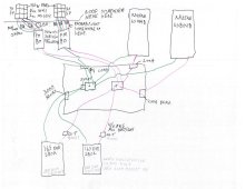
Working on putting together a system. Off-grid only. Have LiFePO4 cells (EVE280K 16s,2p) and panels (18 REC 365W) ordered, working on quotes for SCC/Inverter. Will replace and expand the domain of a current system which draws the equivalent of about 7kWh/day SCC into FLA, Samlex EVO 2200W. Old system is being moved, so figure I've got a clean slate.
How important/useful is having brand of SCC and inverter the same in terms of programming accessories/comms links/controls/etc.?
Current planning to buy:
2 Outback Radian 4KW inverters (2 inverters more for redundancy than expected load)
BMS - read a bunch, but still very unsure what I'll get here. Probably another thread to hash this out.
Breakers, wires, fuses - I've got a pretty good idea in my head what I need, and how it should be sized, haven't quite gotten to laying out specifics. Probably another thread if I need help.
I considered an AIO, but like the notion of modularity in case of failure on the theory that the system degrades less in case of failure with discrete components. And that's before trying to ensure parallel operation.
What I have just figured out is it appears Outback uses proprietary comms, whereas other companies use something more standard. I found this project where someone reverse engineered the protocol for some older Outback stuff, but it looks like nothing Radian is confirmed to work. I tend to very much dislike proprietary anything when I can avoid it. Thoughts on the advantages/disadvantages of this or other brands are very much welcome. Vaguely considered Growatt or similar, but not breaking down or failing that, economically maintaining spares and/or replacing with non-matching replacements, is considered a fairly high priority in selecting components. No SPoF is non-negotiable. I also don't fully trust Growatt idle draw specs.
The proprietary nature of Outback is really what has me wondering if I should move to another brand, but I wasn't as happy with the datasheets on them when I built my comparison spreadsheet.
Notes on any other gotchas or things I might have missed considering here are welcome, too.
Working on putting together a system. Off-grid only. Have LiFePO4 cells (EVE280K 16s,2p) and panels (18 REC 365W) ordered, working on quotes for SCC/Inverter. Will replace and expand the domain of a current system which draws the equivalent of about 7kWh/day SCC into FLA, Samlex EVO 2200W. Old system is being moved, so figure I've got a clean slate.
How important/useful is having brand of SCC and inverter the same in terms of programming accessories/comms links/controls/etc.?
Current planning to buy:
2 Outback Radian 4KW inverters (2 inverters more for redundancy than expected load)
Looked at Magnum PAE: no AC/Gen boost, which seems useful to have; matching SCC expensive and not clearly better for me.
Looked at Schneider SW: Doesn't support parallel operation, would like to have available in case 4kW doesn't quite cut it on occasion for larger draw tools. 7W lower idle spec would have been nice.
Looked at Schneider XW: Viciously expensive, though nice power output, not clearly better than Outback.
Looked at Victron: should be fine, but somehow didn't like the feel of what I read on their datasheets.
2 Outback FM-80 SCCHave experience with this SCC and like it. Two will comfortably handle the full panel output, and the entire array on one in case of SCC failure should provide enough power to be getting on with.
Mate3 & hub - Seems to be required for programming and inverter parallel operation.BMS - read a bunch, but still very unsure what I'll get here. Probably another thread to hash this out.
Breakers, wires, fuses - I've got a pretty good idea in my head what I need, and how it should be sized, haven't quite gotten to laying out specifics. Probably another thread if I need help.
I considered an AIO, but like the notion of modularity in case of failure on the theory that the system degrades less in case of failure with discrete components. And that's before trying to ensure parallel operation.
What I have just figured out is it appears Outback uses proprietary comms, whereas other companies use something more standard. I found this project where someone reverse engineered the protocol for some older Outback stuff, but it looks like nothing Radian is confirmed to work. I tend to very much dislike proprietary anything when I can avoid it. Thoughts on the advantages/disadvantages of this or other brands are very much welcome. Vaguely considered Growatt or similar, but not breaking down or failing that, economically maintaining spares and/or replacing with non-matching replacements, is considered a fairly high priority in selecting components. No SPoF is non-negotiable. I also don't fully trust Growatt idle draw specs.
The proprietary nature of Outback is really what has me wondering if I should move to another brand, but I wasn't as happy with the datasheets on them when I built my comparison spreadsheet.
Notes on any other gotchas or things I might have missed considering here are welcome, too.
Last edited: