


I went down the wrong rabbit hole in a previous thread thinking my LiFePO battery had tanked in the cold, but then saw that a melted fuse/fuse holder might have caused the symptoms (It melted without completely blowing…allowing some current to pass….why I do not know, but it was a cheap Amazon/eBay inline fuse, so current thinking is it was just substandard, and I was “lucky” it lasted this long…and even more lucky nothing caught on fire).
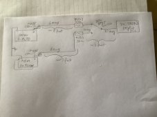
here is a preliminary sketch of PROPOSED / REVISED fusing and wiring. Thoughts? WHAT SIZE / TYPE OF FUSES DO I ORDER FOR THE MAIN BATTERY CIRCUITS SO I CAN GET THIS PROJECT STARTED.
summary of proposed:
* an MRBF fuse on each battery string…wild guess: 80a…could go higher I guess
* 6 ga wire up to a panel, which is easily accessed. The batteries themselves (and therefore the MRBF’s) are NOT conveniently accessible.
* a MIDI fuse at the panel…easy to see and replace, For each string. (say 30a, though if there was a 25a version, I might prefer it). From the MIDI’s, wiresize drops to 10 awg (for <6”) to a “somewhat beefy” 30a switch (NKK S-823D) which controls which battery string is connected to the controller.
* another short (10-12”) 10 awg wire stretches from that switch to the controller. Max wiresize for Victron 100/20 controller terminal is 10 awg. So: battery > 80a MRBF > 6 ga > 30a MIDI > 10 ga > switch > 10 ga > controller
* battery negatives have 6awg wire to bonding busbar (BlueSea 2306 bonded to chassis) 1 ft long from the LiFePO, and about 5-6 ft from the pair of AGM’s). Additional wires to the negative bonding are 2x 10awg (the negative terminals in the Victron are internally bonded, so 1 10awg wire to each (load and battery) in the Victron effectively provides a 2x 10awg path (???), likewise, there are 2x 10awg negative wires to each of the 2 load fuse blocks. I didn’t draw all the load circuits because I was in a hurry, and assume it doesn’t affect the main question: WHAT SIZE / TYPE OF FUSES DO I ORDER FOR THE MAIN BATTERY CIRCUITS SO I CAN GET THIS PROJECT STARTED. Most of the wiring described is already in place, but will change to allow for the new fusing…but an extra pair of eyes or 2 or 3 would help convince me I might be doing this more correctly this time.
* solar is 45-50v 250w (so single digit amperage)
* loads never exceed 20a in practice: 12v fridge, fan, LED lights, water pump used sporadically, occasional 1.5a parking heater, and a couple 12v power outlets (fused at 15a, but rarely used beyond 3-4a phone & tablet charging, rare tire inflator (5a after ~10a inrush) use.
* no inverter
* shouldn’t matter, but there is a Victron Smart Shunt in the AGM negative cable.
in general, I use the LiFePO overnight while I sleep, until fully recharged mid- late- each morning. Thereafter, I switch the solar charging and loads to the AGM, until dark, and after until bedtime (back to LiFePO). So the LiFePO powers the fridge, heater while I sleep…a fairly light load; the AGM powers things afternoon and evening. Neither gets stressed, which is good for lifespan, and probably why the AGM’s haven’t failed yet.
lets not litigate why I have 2 battery strings. I have them, have had this arrangement for ~ 5 yrs as my install has evolved, I have always bought batteries at different times for each string, and didn’t want to mix old and new, and certainly not intermix LiFePO and AGM in the same string, or in such a way they could electrically interact (I don’t think current ever passes from one string to the other, or shared to a load, or from a charger, at the same time. I intend to continue to have this arrangement, though assuming the AGM’s will be the next to die in a year or 2, I would probably replace them with LiFePO When the time comes (They are under the floor board of the van and very hard to access…not trivial install…and near exhaust/muffler, plus more vulnerable to freezing temps.
Attachments
Last edited:


